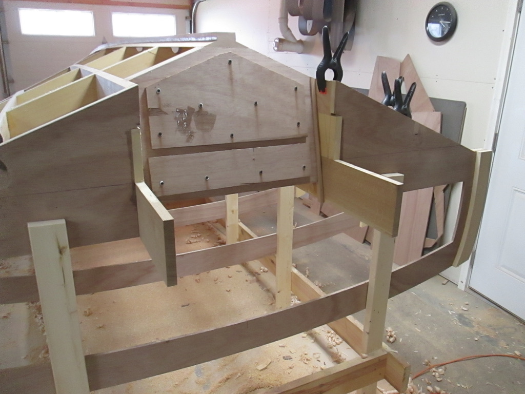
The 1962 Thompson Dash Renew

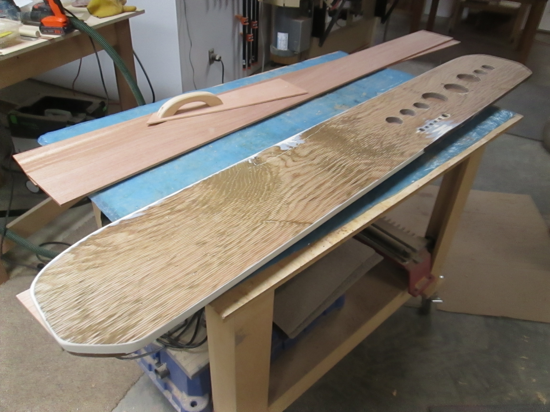
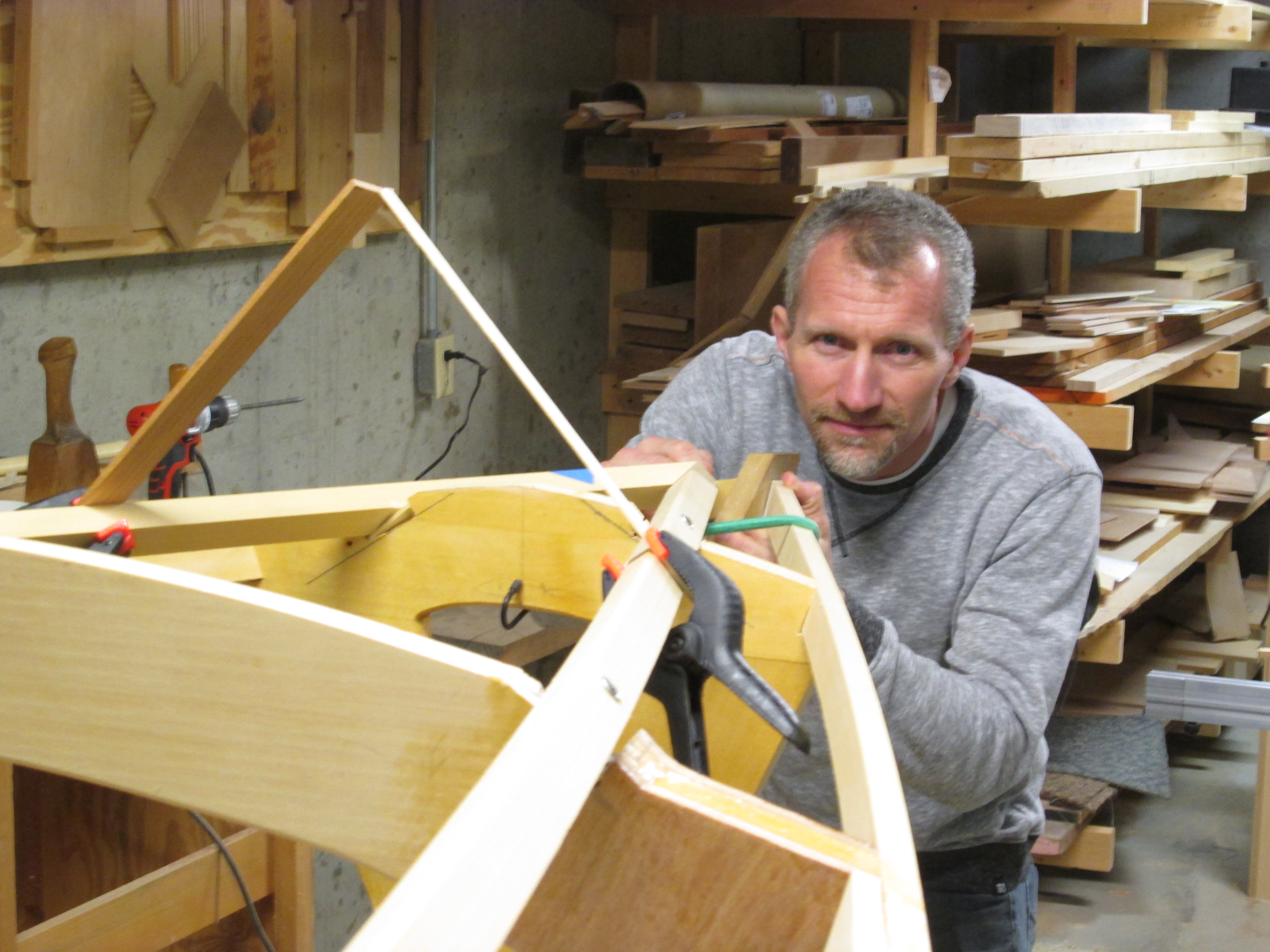
The new boat is a continuing theme, but some interruptions are necessary in a 2-3 year project. The !962 Thompson being restored by Lake Effect Marina in Union, Michigan is nearing completion, but it needed a little help finishing up the dash board. Over the years it had been painted a couple of times over a plywood panel that wasn’t so special to begin with.

Scott is quite an artist with the Hydro dip technique, but getting a good looking Mahogany grain over paint never quite materialized. So he called and I went over to check out the problem. The last time I discussed how he wanted me to fix something, he said, “I have seen your boat. Just do this job like it was your own.”

That simplified the discussion, and the idea carried over to this project as well. So, the first thing I thought was that the dashboard should have the same beautiful solid thick Mahogany veneer as the transom that I rebuilt last December. (see Posts Thompson Transom 1 and 2)

I bought a nice piece of 4/4 Mahogany from Nisley’s Sons, and used my table saw and bandsaw to slice it in two book-matched pieces. Then I jointed the middle edges straight so they would lay together well, and taped them with wide masking tape.

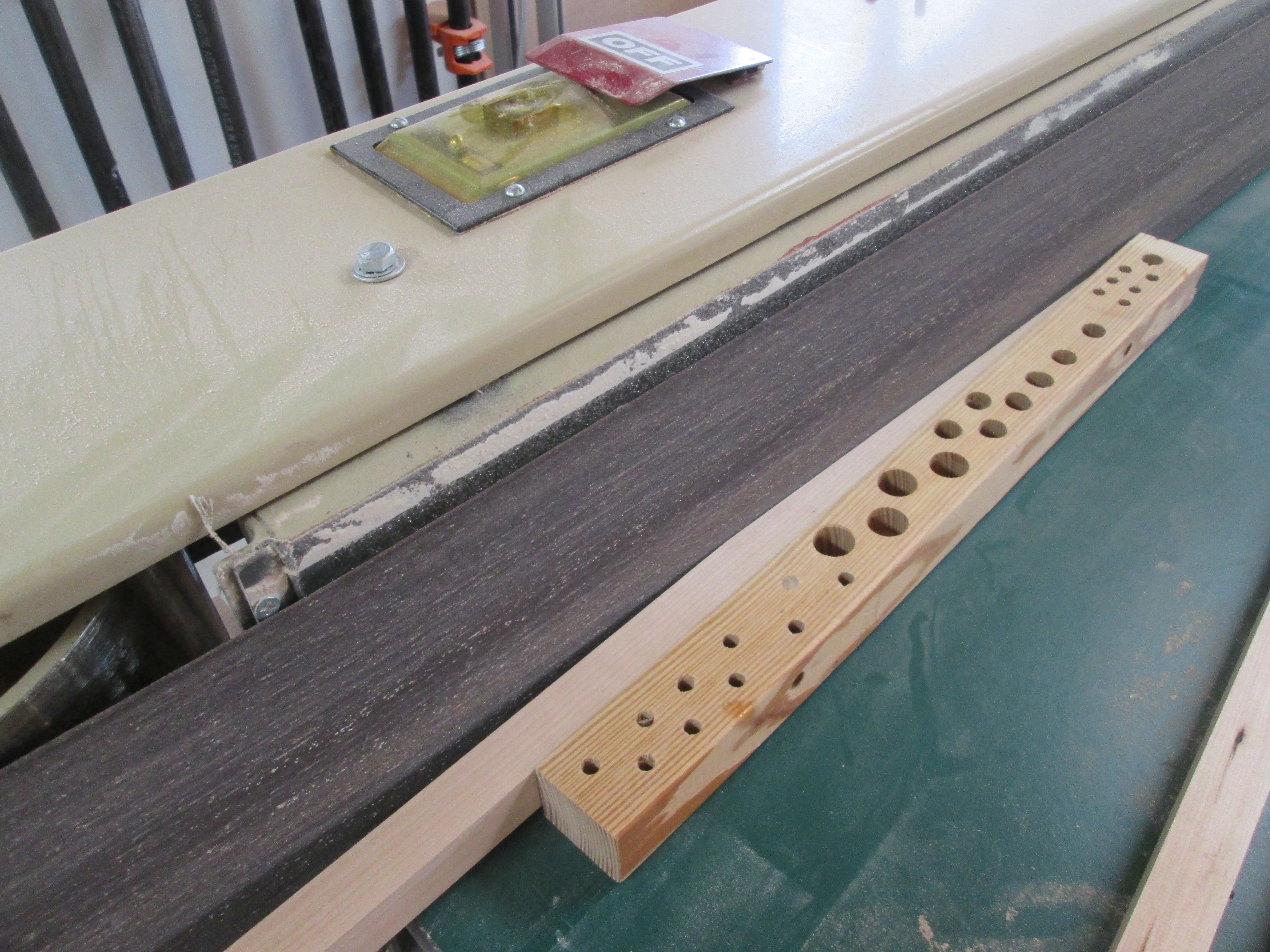
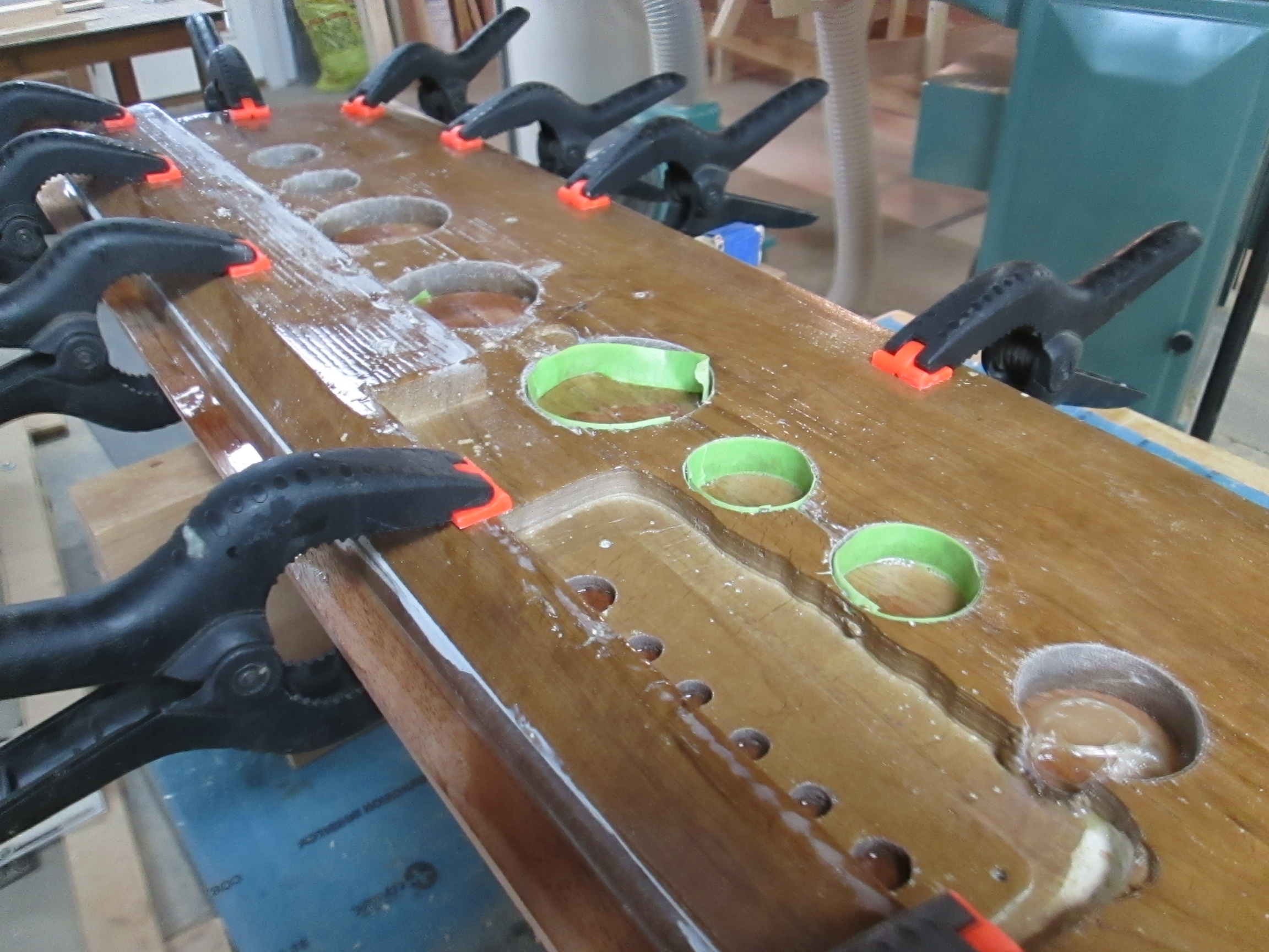
On the back side of the dash, I cleaned and smoothed the holes for gauges and controls. Then, I taped them with green tape so there would not be much epoxy to clean up. The Mahogany veneer was left wider and thicker than the needed final dimensions to make clamping easier and to have less epoxy drip.

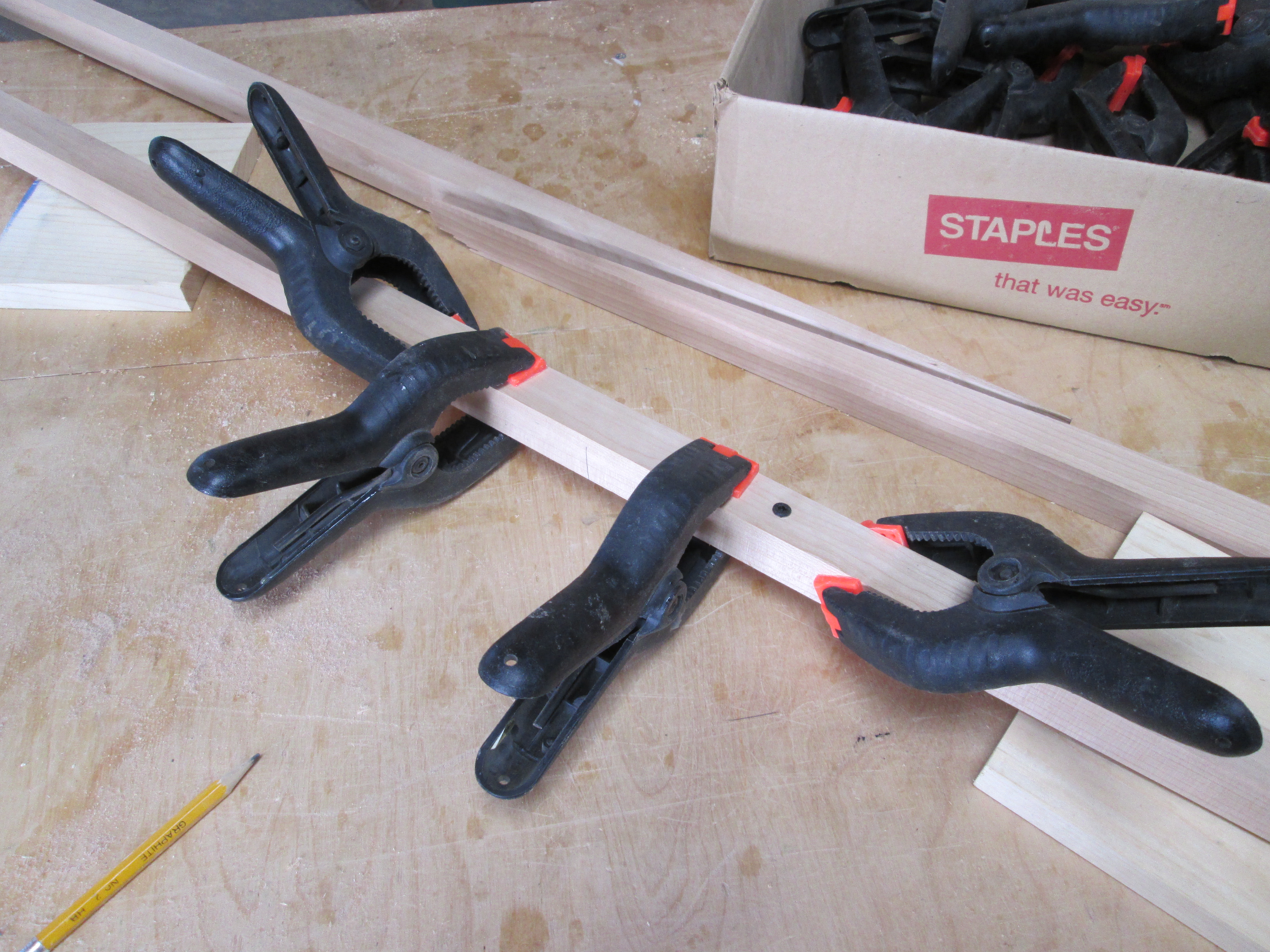
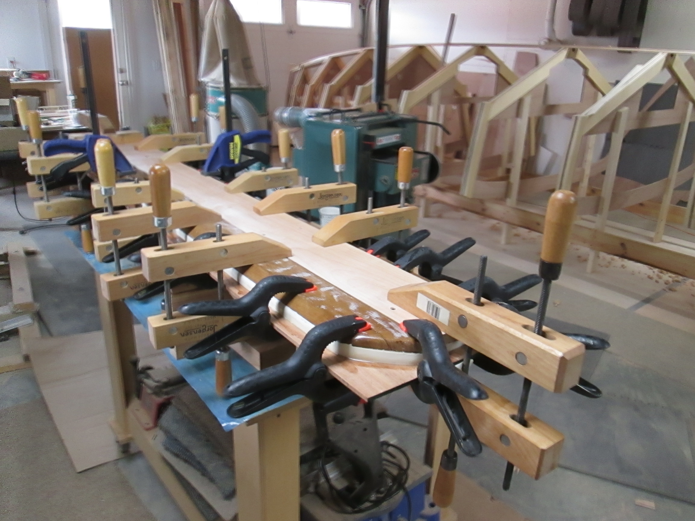
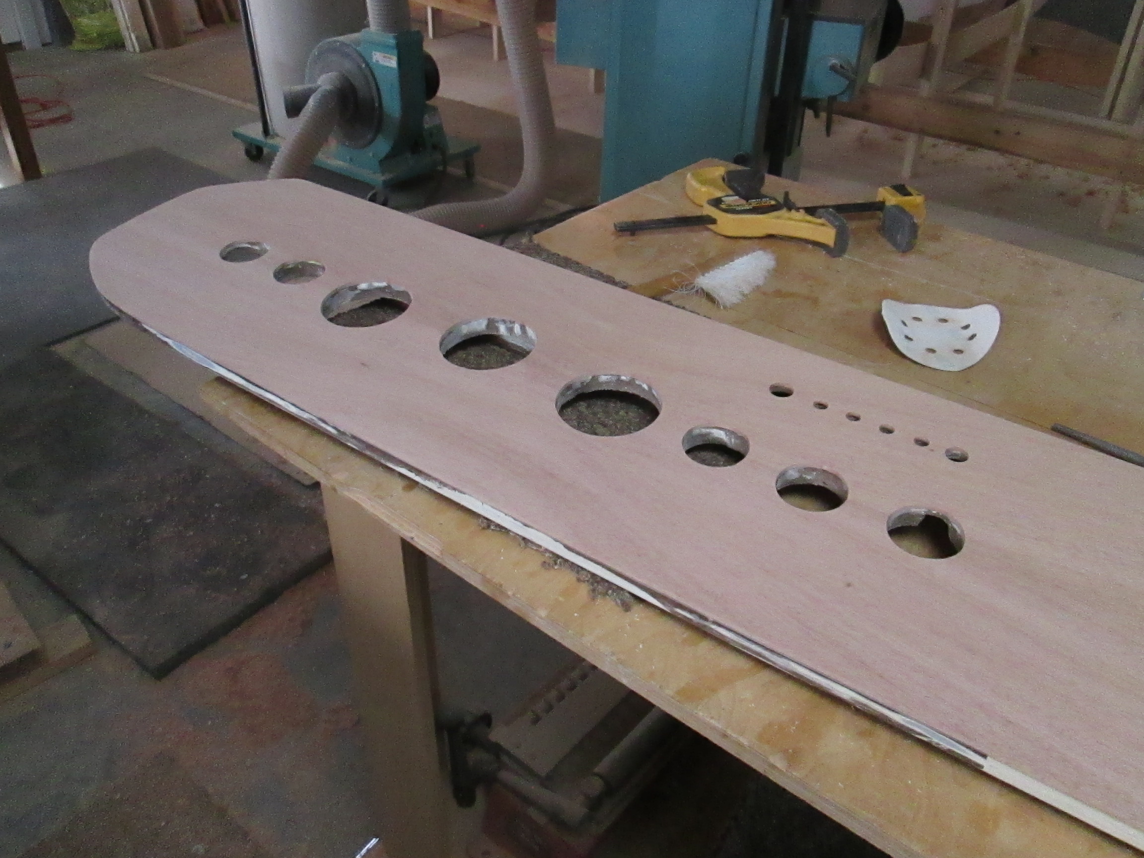
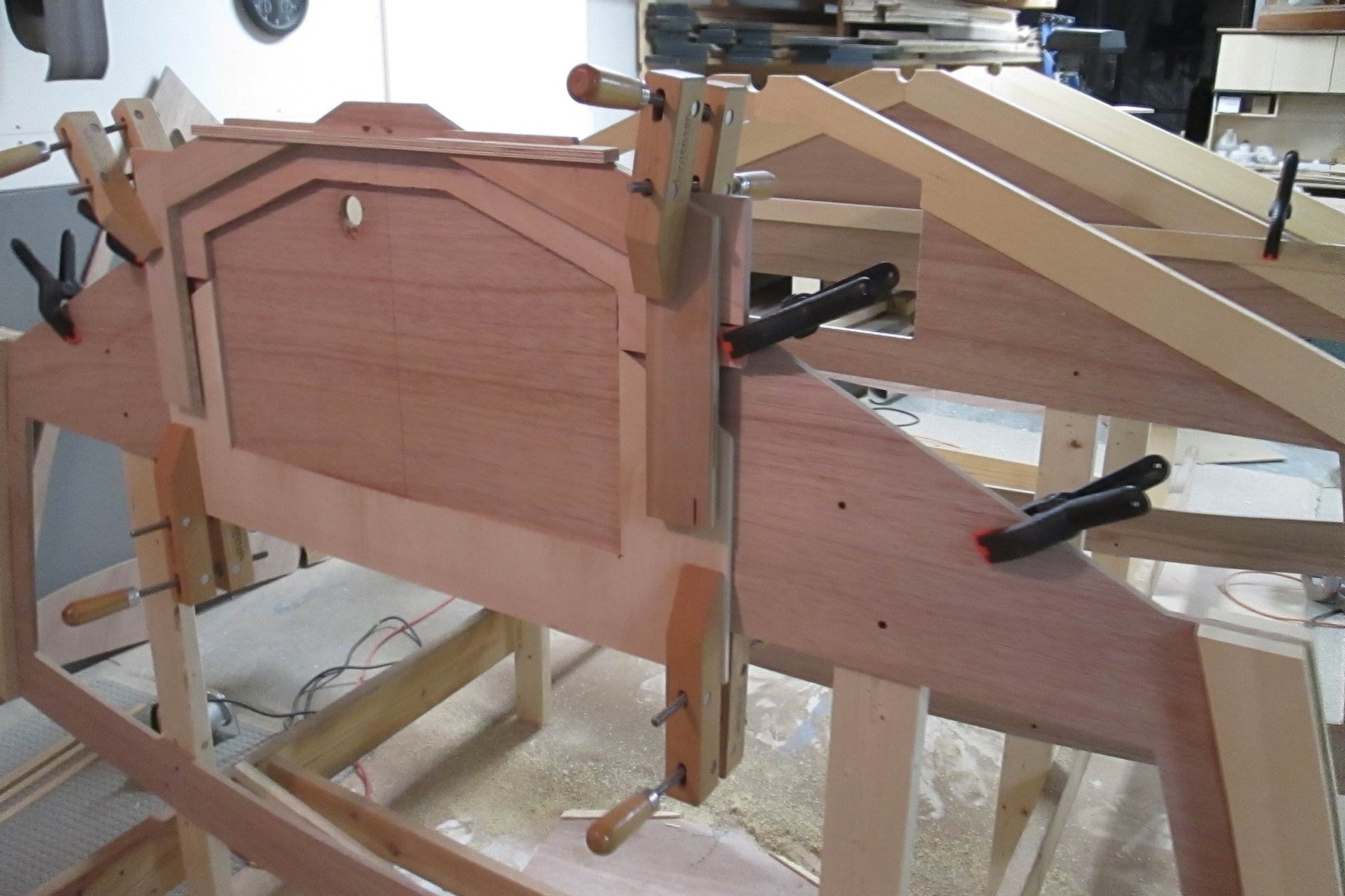
Many clamps were used, with wood blocks on the back side to spread the pressure more evenly over the whole surface. After epoxy bonding, I removed the green tape, cleaned up the excess, and routed the holes out to the original sizes.

Next, the veneer edge was trimmed to the original shape, final sanding was done. The dash was delivered to the marina for them to varnish, mount gauges, and install in the old Thompson speed boat..

If you having a problem with too much work to do or too many customers, you could probably fix it with a few sloppy jobs!

Otherwise, giving a “baker’s dozen” or “doing unto others how you would like it yourself,” will earn a stellar reputation.

Jeff Margush & The Keel line

I don’t remember the first time I met Jeff Margush, but it wasn’t long before the formal founding of the Car, Boat and General Design Club. We met for about 15 minutes, between first and second services at River Oaks Church, but since they did not recognize or promote the club as a ministry, it did not grow very quickly.

The fact that design was not such a popular Sunday school topic may have contributed to its slow kick off. But, maybe a decade ago, we picked up a third member, Bob Herrold, who is a strong contributor when he is not in Florida or other wise busy. We are not super magnetic, as the club is only slightly less popular than this blog.

One Sunday at a clandestine meeting right beside the offering cabinet in the lobby, I mentioned I was thinking about building a boat. Jeff said, “If you want to come over, we can sketch it up on the computer.” He listens better than most anyone and doesn’t do much horn tooting, so I didn’t know how well prepared he was to pull off the idea. Below is a collage of the kind of concept drawing he does.

I asked Jeff for some comments about line/drawing and he gave these thoughts, noting influence from his design mentor, Jim Orr:

“Design is the beginning of the thought process, the genesis of an idea. Drawing is the language of line that puts it in visual form. Generally, the first lines are drawn to create shapes that appear two dimensional. With the addition of more lines, like section lines or perspective views, form or volume can start to become visible.

Particularly when designing moving objects, these lines should be dynamic with movement and emotion. Tone or value really drive home what the form is doing, helping to communicate the design.” Here is a drawing he eventually did, summarizing most of the ideas we put into the first boat.

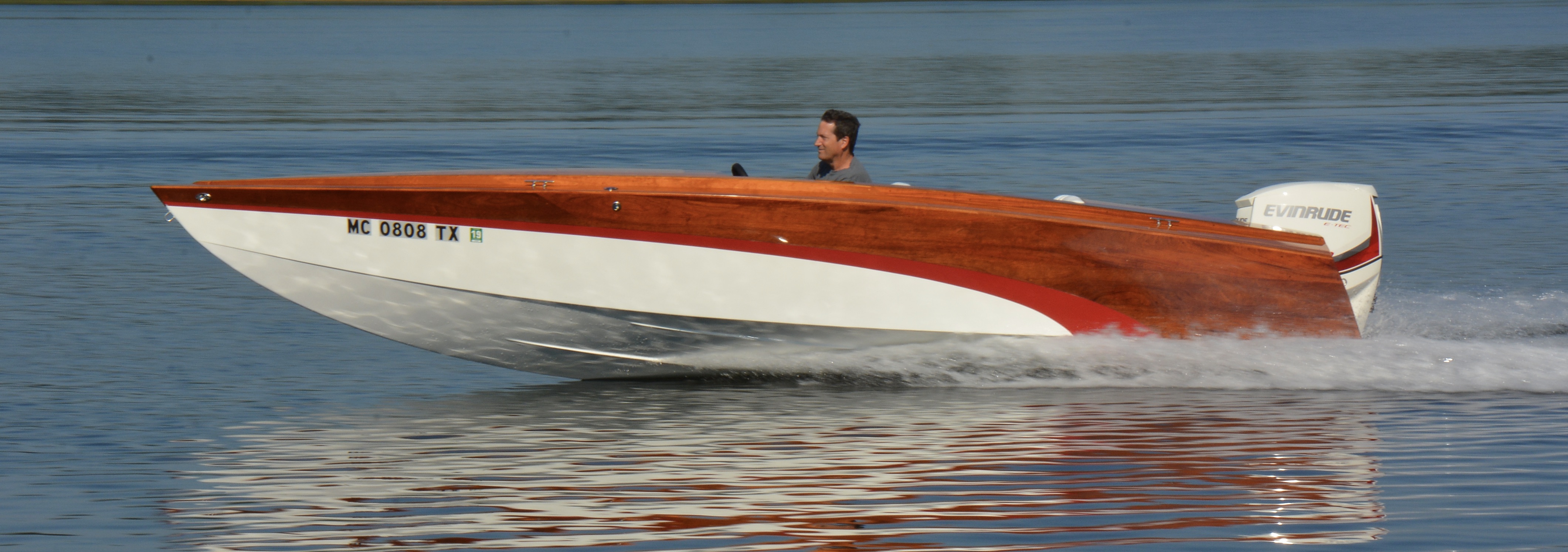
Below is how the first boat turned out. Did I mention Jeff also took the photo? He knows what he is doing.

Since then, I found out that he graduated from Cleveland Institute of Art with a Bachelors of Fine Art in Industrial Design. Then, he went to work at Paramount Plastics, developing interior systems for RV and specialty vehicles. Next on the journey was Newmar Corporation, where he designed exteriors and cockpits for High End Class A Motorhomes.

Most lately, he has been working on exterior and cockpit design for Tiffin Motorhomes High End Class A, C and B Rv’s. His initial concept sketches in 3d files are used to cut patterns for fiberglass tooling. If you know anything about the constant conflict between designers and the producers, there are few people who can cross that line better than Jeff Margush.

And here is an example of promotional material that he did for Tiffin:

Line is also an important element in the review of 3D shapes. Below, Jeff is checking the fairing of the sheer line on the first boat, formed where the hull side meets the deck surface.

On the hobby side, Jeff likes pretty much anything with wheels but in particular sports cars and a special passion for auto crossing his 914  Porsche. When the Porsche club needed a poster, well, Jeff managed to put out an “acceptable” design.

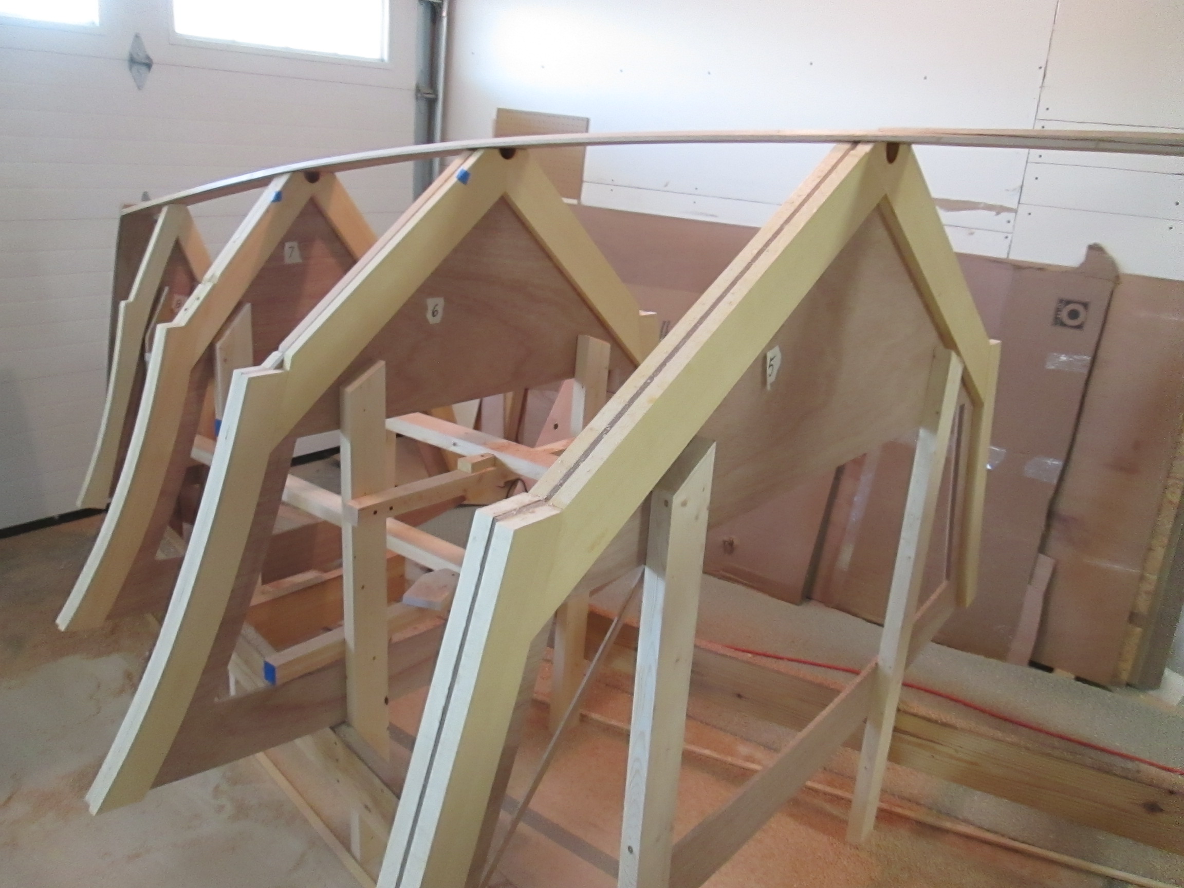
Meanwhile, back in the basement on the new boat, a piece of cherry wood was planed thin enough to bend comfortably on the line from the bow to the flat part of the keel at the back. When I first placed the board across the top, I had to do some adjustment of the frames until it formed a visually fair curve.

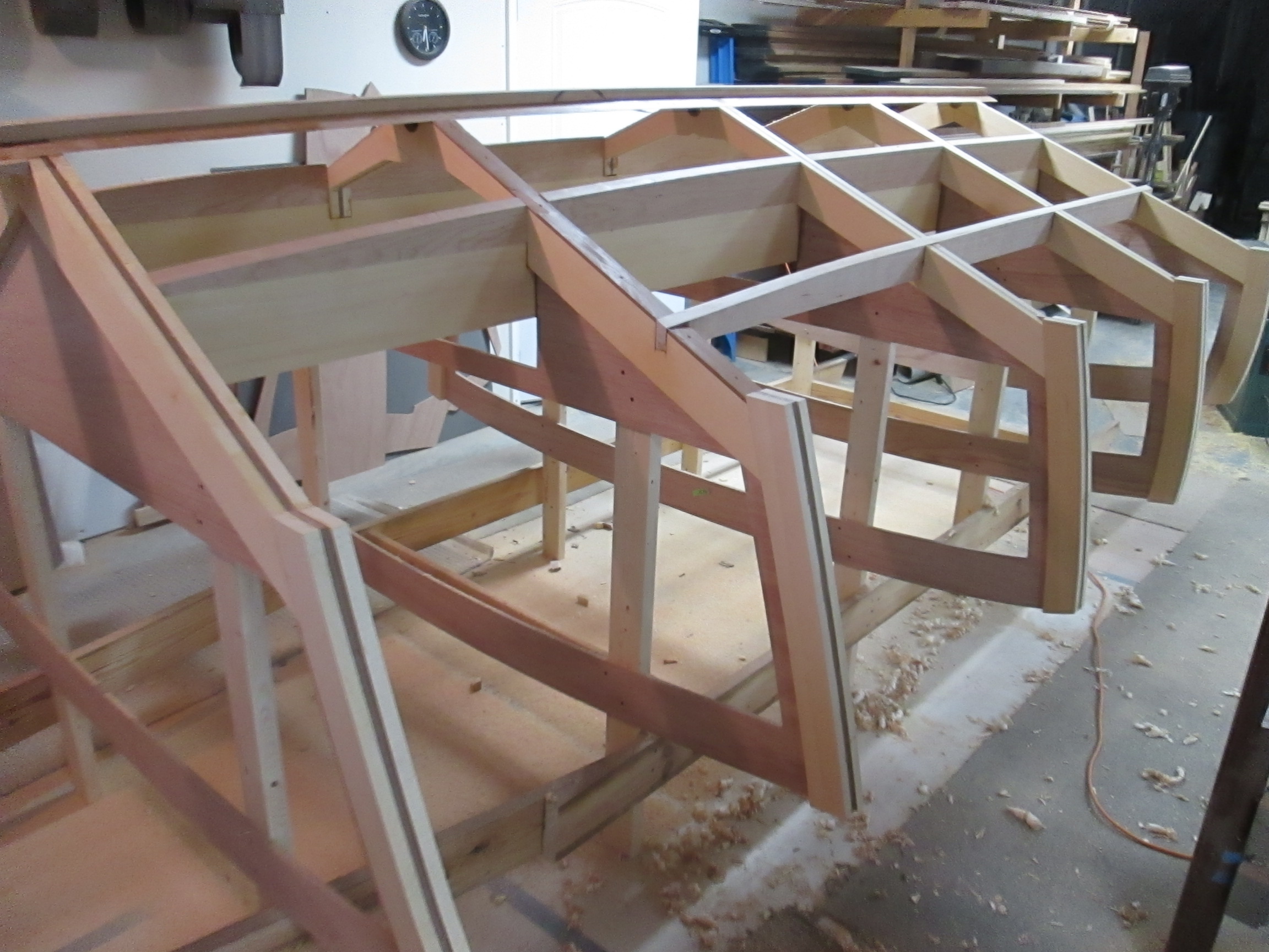
Next, I scarf-joined the bent piece to the straight piece forming the keel to the back.

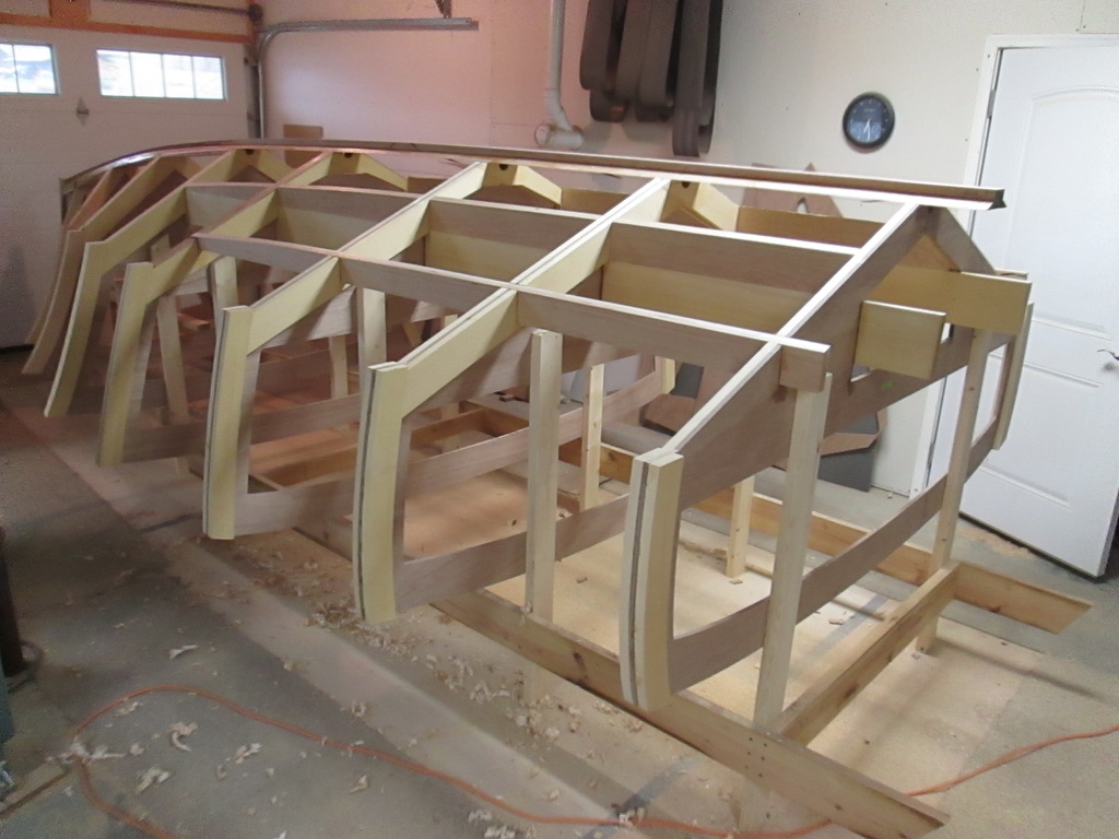
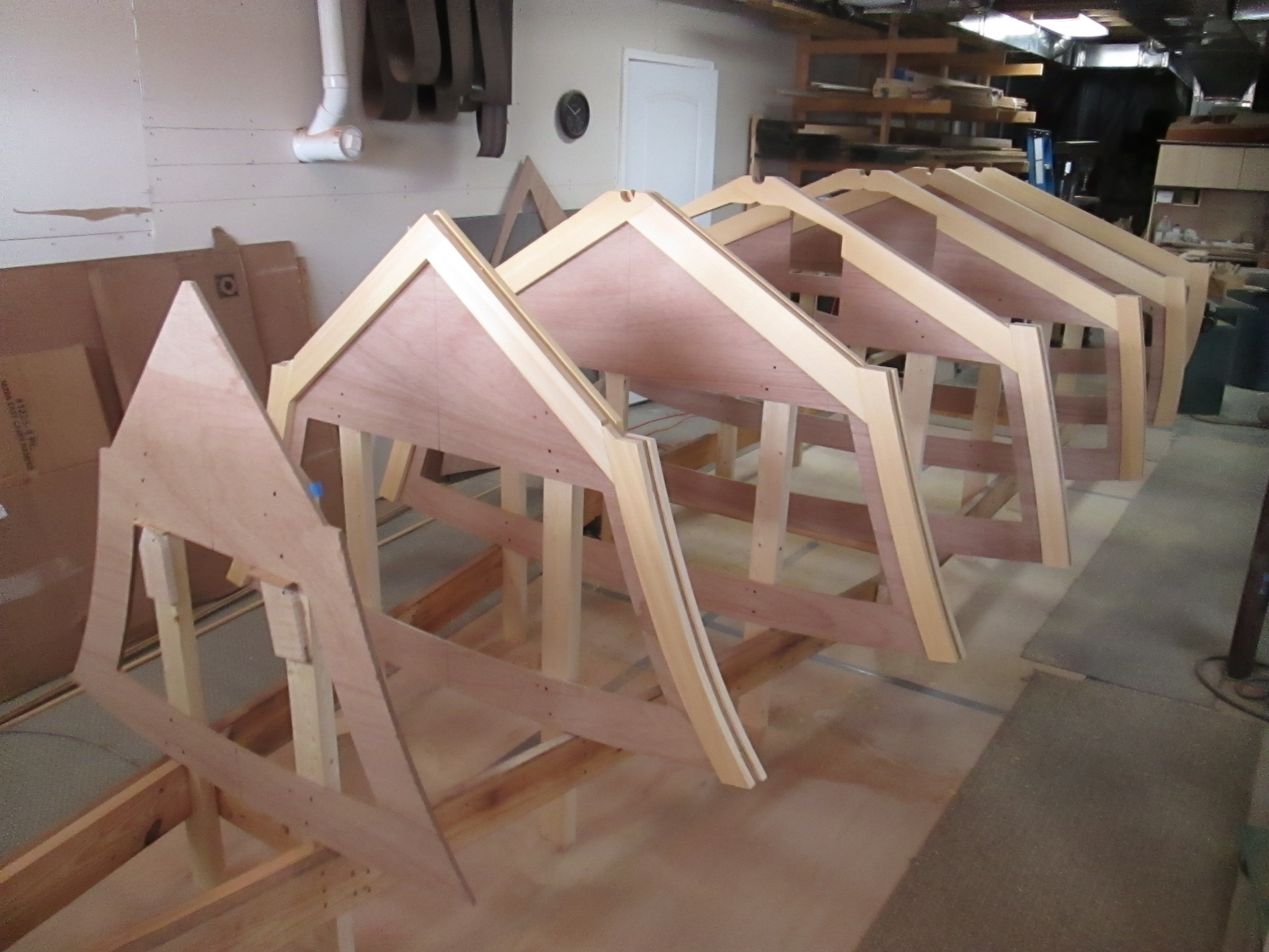
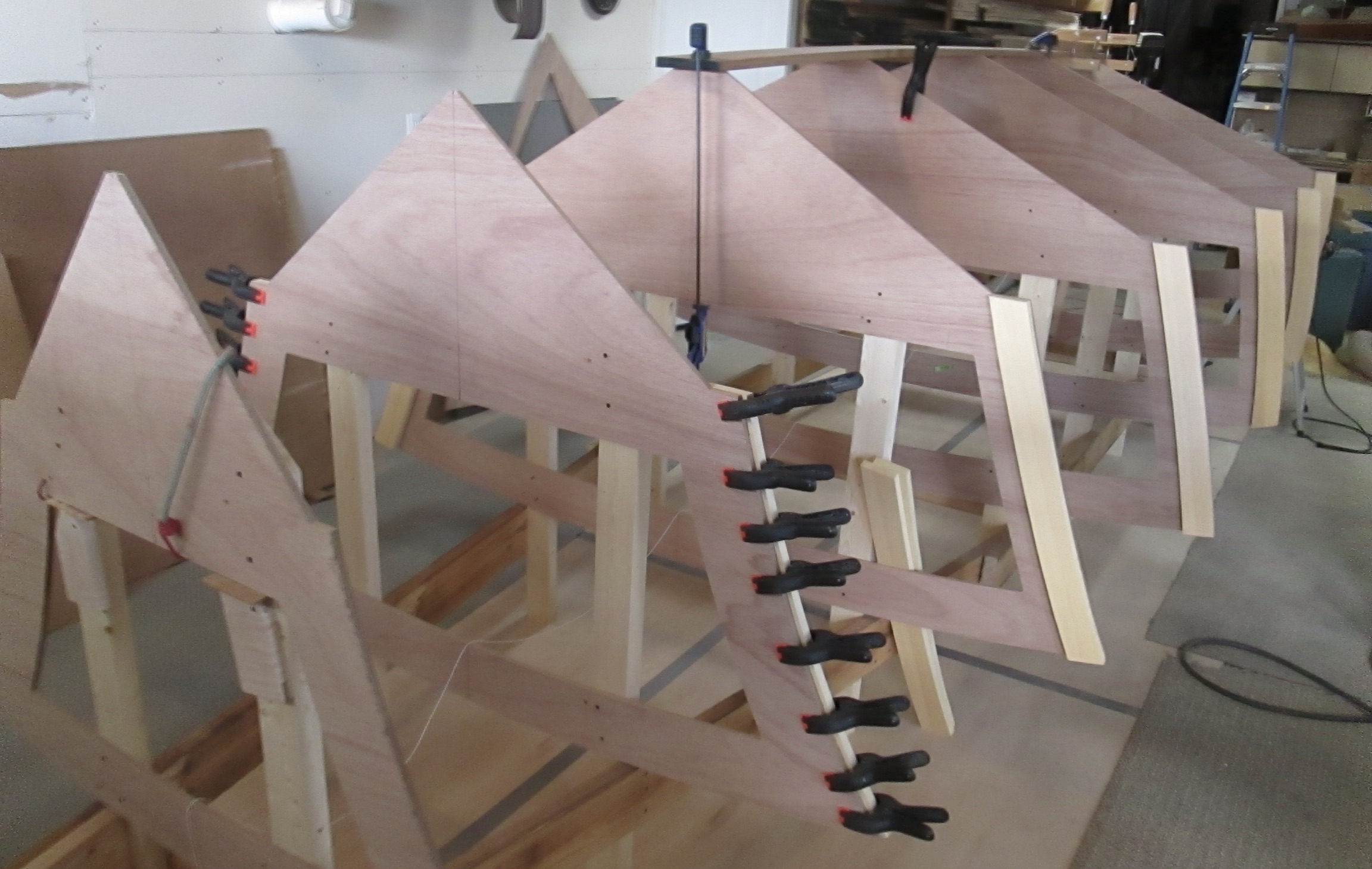
The free standing cross frames of the new boat are now connected and epoxied together.

What’s in a line?

A time line, out line, red line, fine line, yellow line, dotted line, fast line, slow line. Line up, line out. Color inside the lines, walk the fine line, and find the silver lining.

Cross Frame Modification

In a perfect world, each of the cross frames would have been modified in advance, especially considering that the pieces were CNC routed and little more effort would have been needed at that time.  But, since the original computer boat profile was lost, and some guesswork needed to place the frames, it seemed better just to wait.  Setting the floor height and imagining where the fuel tank would go, for example, was easier after the frames were in place.  

The first priority was stiffening the outside of the 1/2″ Hydrotek marine plywood. Fortunately, I had some Alaska Yellow Cedar, left over from the first boat. In the last 7 years, it would have been perfect for furniture drawer sides, solid lap-joint cabinet backs and drawer bottoms, etc. But I never wanted to use it along the way, with another boat in the dreaming stage.

The Alaska Yellow is full 4/4 thickness and 6″ wide planks, 16 feet long, with no knots. It is beautiful wood, but expensive, and I wanted to outline all the edges, with as little waste as possible.

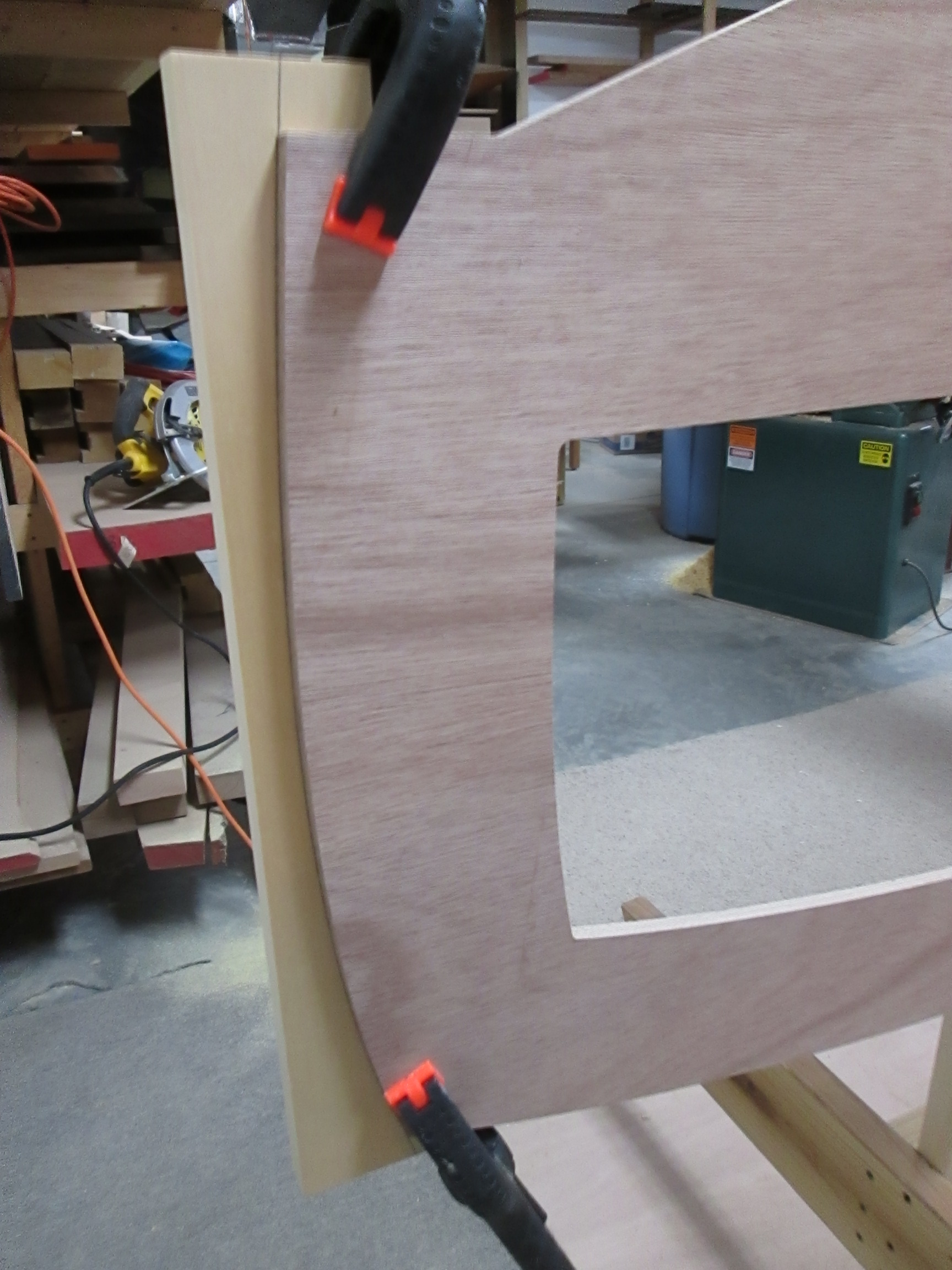
My technique was to cut the 6″ planks into two 3″ wide lengths, long enough for each part of the frame. Then, as the photo shows, I spring clamped the cedar against the Hydrotek, and drew the outline with a pen, roughly in the middle of the 3″ piece. 

Next, I cut the marked pieces on the band saw as close to the line as I could.

When the parts were reversed, with the straight sides together, the outside shape has a very close alignment with the original curve on the frame.

The Alaska Yellow Cedar parts were glued with Titebond 3 glue. It is water proof, and has a better working time than TB 1 or TB 2, and cleans up with water. Titebond 3 is my favorite of all marine bonding agents for edge gluing long grain wood with a good fit.

However, if gap filling or structural strength is required, that is where epoxy shines. Then, it is well worth the effort of extra mixing time and waste, oozing, dripping, sticky and drifting parts, and more difficult clean up. 

Next, I determined that the fuel tank would best fit under the floor from the 5th frame back, so I made a temporary routing jig to guide the router using an end-bearing bit.

At the completion of adding the perimeter frame and center hole cut outs, the cross frames are getting ready for the longitudinal stringers, at the keel, chine and sheer lines.

All of this internal construction will soon be covered, and never seen by a rider in the boat. That is a little like human character, hidden for a while until under pressure, it will show what it is made of.

Cross Frames and the Strong Back

Losing the computer program which detailed how high each of the frames should have been mounted, was a serious discouragement. I no longer had a visual reference for the transom, and the slope the keel toward the bow, etc. There was a few days when I seriously debated whether to quit or try to restart another way.

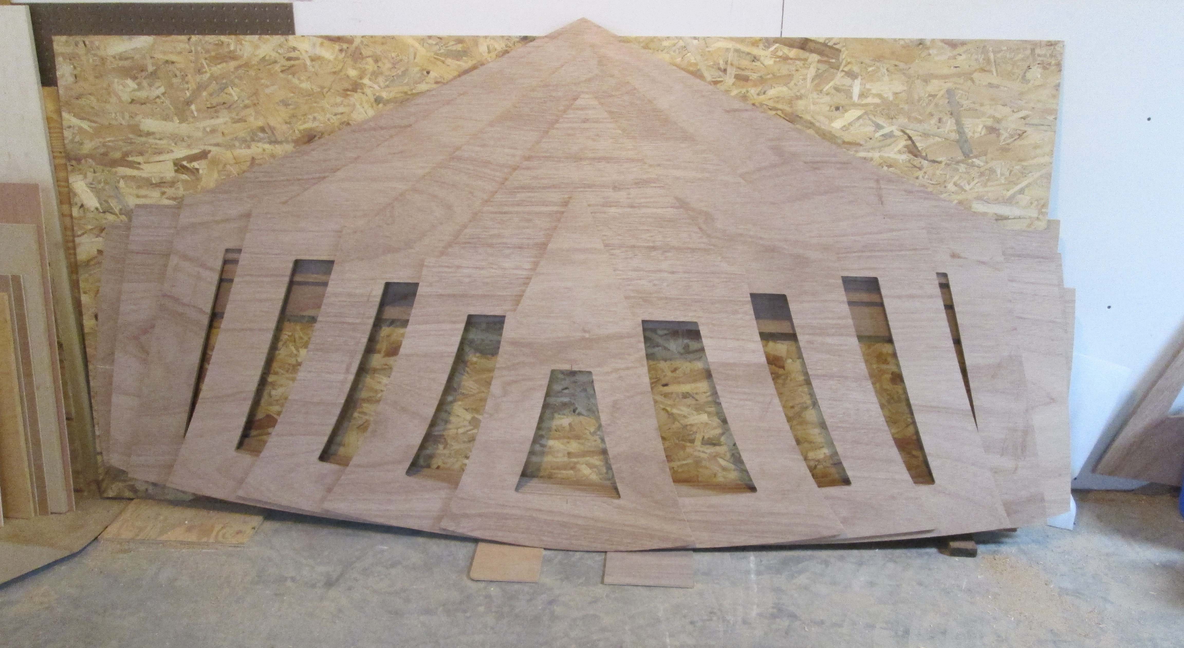
All through that time, the physical frames back from the CNC shop were stacked against the shop wall. It was hard to get motivated to use them, but they were way too big and too expensive to put in the trash.

I did know they were all in the same scale, symmetrical, and I knew their longitudinal positions in feet from the stern: 2.0, 4.5, 7.0, 10.0, 12.5, 15.0, 17.0 and 19.0 feet. In addition, the five near the stern all had the pre-cut interior floor line.

So, I pulled up another similar boat elevation (above) and made some vertical measurements of the top profile. On a table, I lined up Frames 5,6,7,8 and arranged them in a gradually increasing drop down using the height information.

Building a large side to side symmetric object like a boat, benefits from as much precision planning as possible. But sooner or later, when the time comes to create a fair line, precise measuring gives way to the feeling of running your hand over the curve, or inspecting it with your eye. It was far earlier than I planned, but now was the only option to proceed. In a way, it gave me a kindred spirit to the boat builders of previous centuries, who started and finished with little tech help.

The photo below tells a good story of the last few months. Those two desks are for the Butlers, just before going to the finish shop. They are beautiful white oak, with respect for the Craftsman Style, and show some satisfying proportions. Look at the 1 : 1.6 relationships of the drawer heights, the solid leg size, and the strong horizontal top line repeated at the shoulder and at the bottom of the drawers. I already miss having them in the shop!

But success at anything often requires saying no to lots of things. And there sat the cross frames, asking not for a little time in the sun, but for an immediate and long term commitment. It was time to begin winging it.

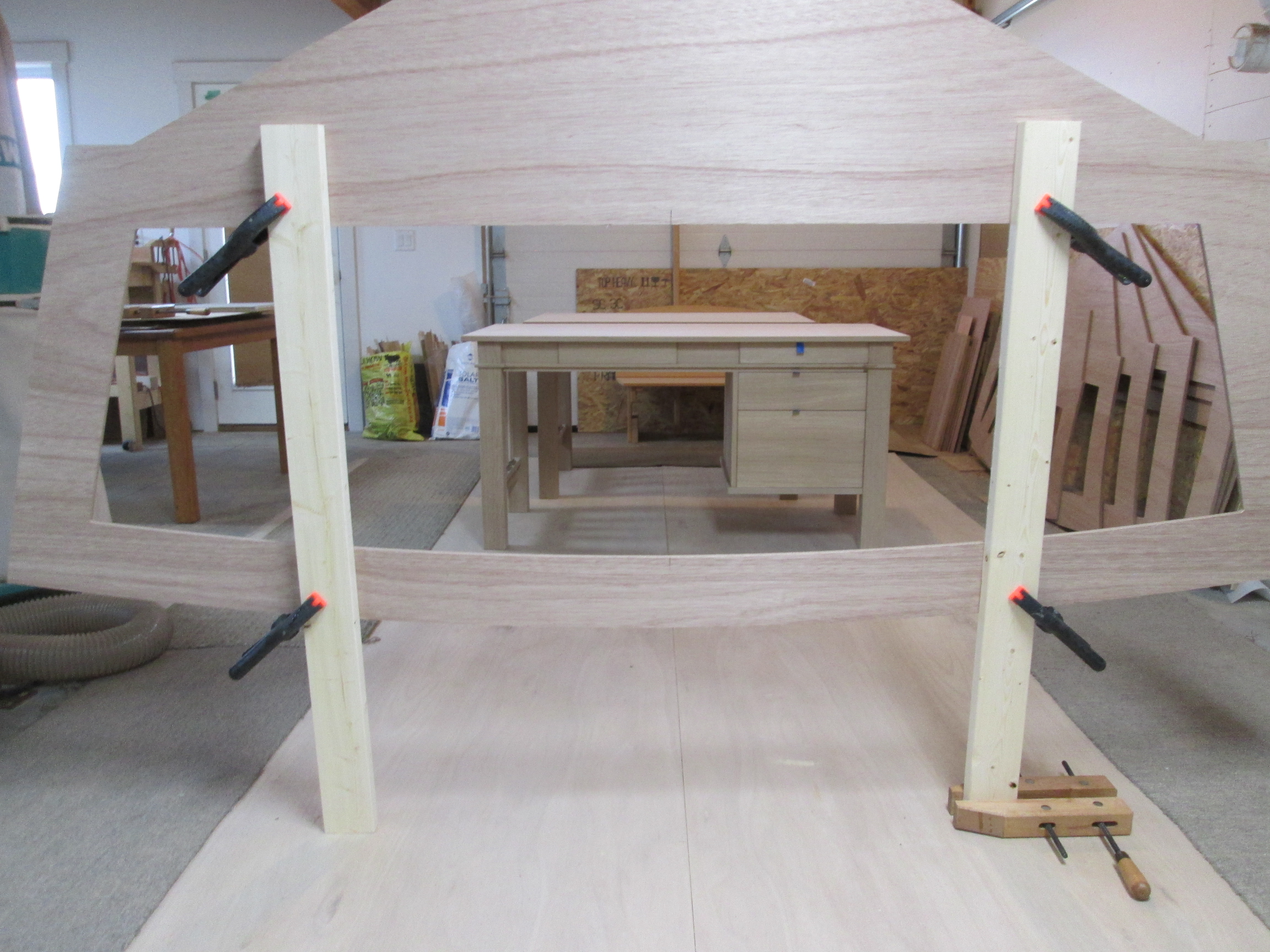
This go around, I did put down some cheap plywood and framed it with carpet remnants to absorb the dirt and epoxy that would eventually create a genuine mess. Then I cut some four foot 2 x 4s and spring clamped the first frame at a comfortable working height. The wood clamp on the floor is to keep the assembly standing up temporarily.

Frames 1-4 are now roughly hung in space, and life is getting crowded as the desks are still holding their own.

Now the process of precision alignment, and building a strong back, began. I used the straightest 2 x 6 pine lumber I could find, put some paint cans under it, and screwed it to the first frame leg, as perpendicular as possible. Then I made the short blocks with an eccentric adjustment hole, so I could turn it a bit up or down, to set the floor line to a consistent height and level side to side.

As I worked forward, mounting each frame, I used several reference points, like the height from the shop floor to the frame boat floor line. Then I used a long straight edges to see if the chine ledge was level as intended through the first three frames. The long curved stick was used to help visualize whether the chine point was developing a lump or fair curve. A large constructed object soon loses perfect accuracy to all of the 3D reference points, but the better related they are in the beginning, the easier at the end.

Finally, I added a post to the front of the frame, with a center string to line up all of the ones behind. Below the seventh frame is going through the same process, setting height and level with the eccentric blocks, and centering to the string.

Another helpful visual tool below was to put small nails at the angle of the chine step, and run a string the length of the frames. By moving your eye along, it is not so difficult to see alignment issues. Frame mounting was all of that, setting height, level, centered, correct spacing, and review of the places it should be straight, and where curved fairly. Then it was time to call it good enough.

Life builds in many tests of commitment. With a little persistence, creativity, hard work, and a lot more persistence, you can get back on track . . .

The Best Laid (Boat) Plans . . .

The new speed boat is coming together sweetly:

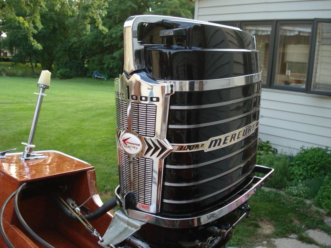
It will be 20′ long by 7’6″ weighing about 2100 pounds, and capable of carrying 8-10 people. This will be powered by an outboard motor of 150-200 Horse Power to push the boat to perhaps 45 MPH. At 450 pounds, the outboard delivers a much better power to weight ratio, and sitting right there on the transom, makes for easier maintenance. An old Mercury 200 Tower of Power like the one below would be the perfect attitude, but then, there goes the ease of maintenance.

The new wooden speedboat will follow a similar construction plan as the first, built of wooden cross-frames and stringers. This time, however, I plan to use a more local variety of wood, starting with the lumber left on my racks from a decade plus of projects. This will include some White Oak, Alaska Yellow Cedar, some Mahogany. These are from long and straight boards, with no knots, and rot resistant.

But my 10-12′ American Cherry lumber is also great to work with, and can be sized appropriately for the strength and function needed. Building a hull stiffened by fiberglass cloth, embedded in epoxy to keep the water out, is a far more important factor than the wood type.

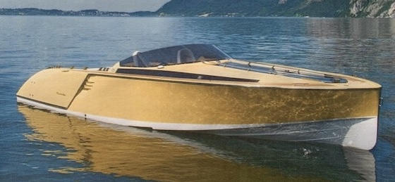
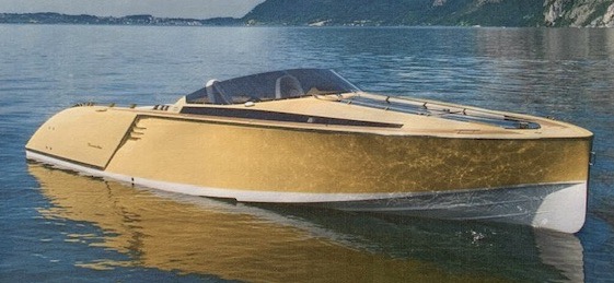
The design concept has firmed up as well, taking inspiration from boats like the Frauscher below.

Some examples of work from my design program are shown below. This is not exactly the boat I am building, but it shows what fun a fairly simple program can create.

The boat shown below is also not the exact model I used for the frames. It does however, show a more vertical bow line, and forward leaning transom above the waterline.

The first serious step towards production was making a series of PDFs of the bulkheads from my boat design. Below is cross frame number 6, third from the front. My old computer with the free boat design program is 25 years old, and with my lack of tech savvy, I hoped that it could still be used.

One day I came to the moment of truth. Was this to be only a design hobby or am I actually going to build a boat? I called Tyler at Cutting Edge CNC in Millersburg, Indiana to ask if he could use the PDF’s. He said that it was quite possible and he would give it a try. In few days later, he said bring the wood!

For the last boat, (frames shown on right), I used large patterns and assembled all of the frames from Alaska Cedar and Marine Plywood parts.

This time I am trying a different approach, having the frames cut from 4 x 8 sheets of Hydrotek plywood. Then I will reinforce them later.

At Johnson’s Workbench in Charlotte, Michigan, I bought the 6 sheets of plywood, and dropped them off to Cutting Edge. Another couple of weeks, and voila’ the possibility of a boat became real!

After I received the cross frames, I went back to my computer design program to review the actual model’s side view lines. This was for the final information about how to position the bulkheads vertically, especially the front 3 or 4.

With apparent careless habits from new computers, I did not press save one time, and experienced the unfortunate disaster of the old days of computing. The current design concept was not shown above. . . because it is gone.

None of my efforts, or advice from experts to recover the design worked, and there I lost many hours of irreplaceable work. There is a lot about building boats that is like life.

Till next time . . .

Intuitive Boat Hull Design

The physics and math of fluid flow across a hard surface is pretty complicated, but taking a common sense approach can bring a good bit of direction to a new boat design. The first main decision is whether the boat is supposed to go slow or fast.

Slow, displacement boats when moving, stay nearly at the same depth as a rest. Speed limits are defined mostly by the length of the object, and the length-to-width ratio. The row boat below is beauty in motion, although quite slow.

This God designed hulk of a whale is a far more efficient displacement machine. Even though it has to push its full girth through the water, It has a super slick motion, with speeds exceeding 20 mph for short distances.

Wood boats can’t begin to replicate all the whale’s body mechanics of flex and fin stroking. But, human engineers have done some of their most successful design work, imitating performance seen in nature.

Another group of boats are called semi-displacement, for their ability to go efficiently at a slow cruise, and still go beyond displacement speed with more power. Generally, the more pointed the front, the less effort to go forward. A catamaran uses two hull halves to make even narrower parts, with sharper entries.

At the back of the boat, the deeper it sits, the more wake it produces, and the less efficient the power-to-speed ratio. Below is a fine design of a semi-displacement hull. The front of the hull is a cutting edge; the water flows to the side and under the boat. By the time it gets to the transom, the water returns almost up to the original water line. That leaves very little turbulence, or wake drag.

But that’s all academic if you want the boat to go fast, with grab rails! Fast boats are designed to ride on top of the water, and have to be powered strong enough to push the hull up on plane. Then the water touches a much smaller friction pad, generally the back half the bottom or even less.

The contact area is smallest on a flat bottom like some of the old traditional woodies, but that gives the most pounding ride on choppy water. Ocean racers like the beauty below use a steeper dead rise angle from the bottom to the side, up to 24 degrees, giving a more stable and comfortable ride for aggressive wave hopping. By the time they power up their twin 450’s, they may have only the back third of the boat hitting water, some going over 100 mph.

Principle 1 of intuitive design: Define your speed goals and imitate success! I have reinvented the wheel enough times to realize a bike really cannot steer from the back tire, for example.

Principle 2: slow boats are usually wider to their length, and fast boats get narrower. The ocean racers generally are at least 3:1 length to width. My first boat was 20 ft. long and 6.5 ft. wide for a slightly more than 3:1. However, for a smaller boat, it gives up some lateral stability, and overall carrying capacity. The new boat will be 20 ft. to 7.6 ft wide or 2.6:1. This will provide the extra buoyancy for a few more grand kids to jump on.

Principle 3: the dead rise angle. The Raveau Racer above, built by Bob Walwork, has a flatter bottom angle. It is a single purpose boat, run mostly in calm water, as the Raveau drivers tend to be addicted to speed.

For my boat, I have narrowed down to a more general purpose speed boat, with 20 degrees dead rise, which seems to be a pretty good mix of a comfortable ride on flat water or some more choppy conditions. it is some guess work, but some things in life don’t have mathematical answers.

If you look at the bold black outline, you can see slight tip in at the transom, or stern. This “tumble home” is a consistent characteristic that will make it feel comfortable around the old classics. Nearer the middle of the boat, the green Number 3 cross frame, shows that the outside of the hull has a slight outer tip. The light lines show this tip out angle increases more towards the front of the boat, to keep water spray out.

Do a little research, weigh the options, try to evaluate the pros and cons, and then there comes a moment of decision.

More to come. . .

Speed Boat Design 1

A new boat! The original 2016 LC20 “Redemption” was a grand learning curve, and a great success in many ways. The first boat was more like a sports car, where “look good” and “go fast” were pretty much the key intentions. But Jan had some bigger functional parameters of her own, along these lines:
“Well, maybe enough comfy space for a few of my friend groups, like 10-12, or 15 if mostly grandkids?”

“Maybe some drink holders and a cooler, a little party table?”

“How about an easy way to get back on the boat, if we do “diaper dipping,” a form of swimming with an upside down life jacket?” Should I even encourage that?

“Honey, it sounds like you are wanting a “Pond Tune” boat!” I said. “I am sure I don’t have room in the basement for that size of a boat, and I have never seen one done as a “Woodie.” The Kansas relatives above, Marge back left and Ed, second from right seem to be having a great time on Pete’s Puddle, if my reimagination serves me right.

Well then, Jan asks, “How about at least putting a few grab bars near the shotgun seat in case of mild turbulence?” Okay . . . there was the one time, we went for a slow cruise on the wooden boat, and a monster wave surf boat came cruising by, pushing up a four foot wake.

Instinct from driving a 16′ Marlin Scorpion speed boat in the 70’s took over, and I might of goosed it a bit just as we neared the edge of the wake, on an angled approach. The neighbors said we went airborne, including the motor, and Jan went from sitting high at the peak, to disappearing under the dash into the front cuddy on reentry to planet earth.

Being the doting and sensitive husband, I noted the important take away: add some grab bars!!!

A second accommodation for the new boat was drawing a wider beam, going from 6’6″ wide to around 7’8.” This design change adds extra carrying capacity, for that 8-10 plus chatty friend or family group, and will create better side to side stability.

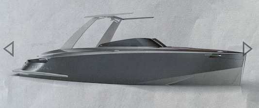
The first wood boat, shown above, was modeled after the ocean racers, with a more pointed bow line. On the sketches for the new boat, e.g. below, I tended to draw a more vertical bow line.

This leans more along traditional lines, but some contemporary boats have used a near vertical front as well, and I find this example quite inspiring.

This time a windshield will be in the plan . . . stay tuned.

Boat Building Wood 2

Besides the Alaska Yellow Cedar, here are my observations about several more of the wood species popular in boat building:

White Oak – This is a tough, hard, strong, and rot resistant wood. It even has fashionable flavors. If you prefer, you can get the contemporary quarter sawn straight grain without the flake decoration. The market price is reflecting that popularity right now, as it is used in much furniture. You can visit a nice example of this style in the blog titled Butler Desk.

If you appreciate the flake pattern of the quarter sawn variety, it is a common trademark of the historic Craftsman Style furniture. In either case, quarter sawn white oak is very dimensionally stable and useful in boats. Since it is also quite heavy, I used white oak for the keel of my first boat, and other parts near the bottom to keep the center of gravity lower.

White oak is a good wood to steam bend, but as a general rule, I don’t like steam bent parts. They don’t follow perfect curves, as knots or grain variation affect the result. Much more satisfactory for me, is to cut the wood in slices which can dry bend the curve I need. With a three or more piece lamination, they self correct and create a beautiful curve without much need for additional fairing. The photo shows the three oak pieces making the chine stringer.

White oak might even be my favorite wood if hadn’t been for leading the entire field of wood entries in the competition for poking splinters into my hands.

Mahogany is next up. It is beautiful, strong, works well and is rot resistant. So many woods go by the name mahogany, including most of the souvenirs you might buy in a foreign country, that it gets confusing. For me, it needs to be the red brown variety, most likely from Africa, more dense with not so much grain porosity, and beautiful figure. This prime wood is expensive, but worth it in the most demanding circumstances, as shown by the number of classic boats it covers.

The Mahogany below, on my first boat, came to me a long time ago from a Swartzendruber Hardwood Creations garage sale of unused boards. It stayed in my shop 10 years or so before I had it sliced into 3/16″ veneer and put on the boat. The lighter top veneer planking is Curly Maple, which is does not compete well in boat building categories, except beauty.

Marine Plywood is most commonly available in two species, Okume and Meranti (Hydrotek), and an integral part of contemporary wood boat building. It has meet International standards for glue strength, water resistance, and having no internal voids.

Plywood is much more dimensionally stable than any solid wood, and as the inner core of a composite layer, it can make an exceptionally strong, curved surface. In my first boat, I used tongue and groove marine plywood hull planks, covered inside and out with fiberglass cloth embedded in epoxy.

There are no leaks and not much water ever gets in the boat, so rot resistance of interior parts is not a problem as in the old woodies. I prefer Okume plywood for its light weight, but used Meranti, (Hydrotek), for the cross frames, as it is cheaper.

I will return to Okume for hull planks this time, as I find it easier to fair with hand tools, and sanding boards. However, using T & G planks gives a self fairing head start.

This time around, I am looking around my shop, using some inventory hanging around for awhile, and buying the rest locally in Northern Indiana. The interior will likely be mostly Cherry. It is medium in weight, strength and shock resistance, but good for bending and it works so well with machines and hand tools very well.

The decision for the deck wood is still uncertain, but if I find a particularly gorgeous curly spalted maple plank, I might ignore the rules . . .

Boat Building Wood 1

The design of a new wooden boat requires thinking about the choices of wood. Trying to keep the water out of the floating space takes a combination of strength, stability, toughness and endurance. Western Red Cedar, Alaska Yellow Cedar, Sitka Spruce, cypress, teak, ash, white oak, and mahogany are some of the most highly prized woods for the beautiful traditional wooden boats of the last century. 

Some physical properties that matter most for the wood in a boat are: strength, density, hardness, stiffness, bending properties, moisture resistance, and dimensional stability. From a practical standpoint, some of those factors may be overridden by cost, being able to source them close by, and working ability. With all of that in mind, here is one of my personal favorites:

Alaska Yellow Cedar – It is not cheap, in 2023 around $10-15 / board foot rough. But everything else about yellow cedar is amazing. Mine came in generous 4/4 thickness 1″ x 6″ x 16 feet long with no knots. The prime vertical grain boards are straight, lay flat, are very stable and weather resistant. It is very light weight, and has an exceptional strength to weight ratio which is great for boats or airplanes. The distinctive aroma advertises its unique personality, which is like your Grandma’s cedar chest, spiced up a bit. 

But it really shines when you actually pull it off the rack and put it to work.

Alaska Yellow Cedar cross frames and stringers.

The tight consistent grain cuts so consistently and smoothly, that it makes hand tools seem like a good idea. A bonus is that it over a few years working with Alaska Yellow, it has never once given me a splinter. I love this wood.

Perhaps you can imagine how sorry I am, that the original stash I bought in 2013 to start the first boat is coming to the end.   But, there are other wonderful wood choices . . stay tuned.

Butler Work Station 2

The Work Station has all of the detail of the desk, but with the drawer cabinet discretely tucked into the right inside. The molding being added below is at the same height as the cross piece on the side, making the cabinet look like it meant to be there.

The horizontal molding is far more secure at the corners when placed into a groove, so this is the jig to hold the router as the cut is made.
The trim is planed to the thickness of the groove, and the long pieces fitted on the skirt board are glued in place first. The small L-shaped pieces are then made, partly on the bandsaw and with small holding helpers on the table saw.
Gradually, both end miters are cut back to fit the moldings at both corners. Then it is sanded and glued into place.
Try as I might, white oak likes to pull surprises, and this small knot hole was begging for attention. So I made a face grain plug, glued and sanded it flush. With a casual inspection, it can be found, and in one more way reinforce that it is a desk like no other.