The Bow Line

The first boat had a more pointed bow and stem line. but on this one, I wanted to show respect for traditional speed boats in the concave surface under the front area, a touch of the barrel back shape at the stern, and that more vertical bow line. Besides, a vertical bow line can look beautiful on either a traditional or contemporary boat.

It was a casual thing to sketch side and top views, and the difficulty to design it on CAD was mainly figuring out how to use it. The program even had a color warning if too much angle change was occurring over a short distance. This is not exactly the boat I am building, but I obviously did not notice the bend and twist needed on the lower front area.

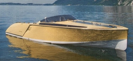
Had I done more research, I would have found myself in good company. Below is an expensive European Frauscher runabout that shows a vertical bow line relatively well designed, although by running the chine so high, the sides look a little like fat cheek jowls.

Below is another Frauscher with a vertical bow line. It might look good from the front, but at this angle it just reminds me of a turkey wattle. Cut that weak, skinny piece off of the lower front, and there is a pretty boat left.

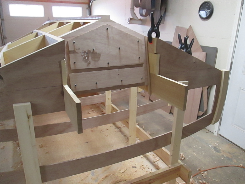
So here I am, trying to create that strong, vertical line, that looks good from all angles. Somebody should have told me it might be impossible. On the other hand, I have collected several examples images of vertical bow boats that must have encountered the same design challenge.

  1. This is another inspiring Frauscher, but when it gets up on plane, the front end might talk turkey.

2. The Herman Form 29 solves the visual side, but there is still the angle/bend problem at the blue line.

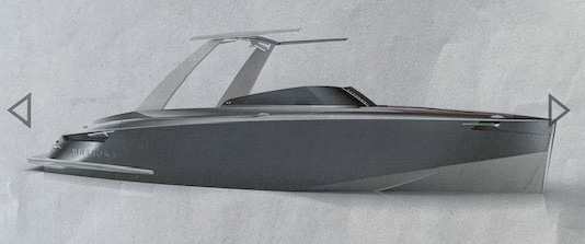
Below is a contemporary beauty, the Gilbert Creative Muskoka. I would like to see what is under the water.

Of course, friend Jeff also drew a compelling piece of poetry in motion, and it looks like the dropped chine line may contribute to an easier go at the front. I will have to ask him how this 36′ Cruiser was to be built.

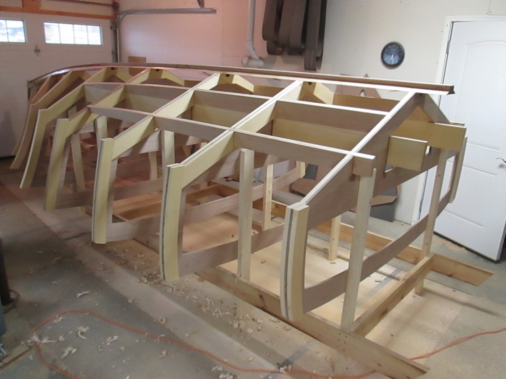
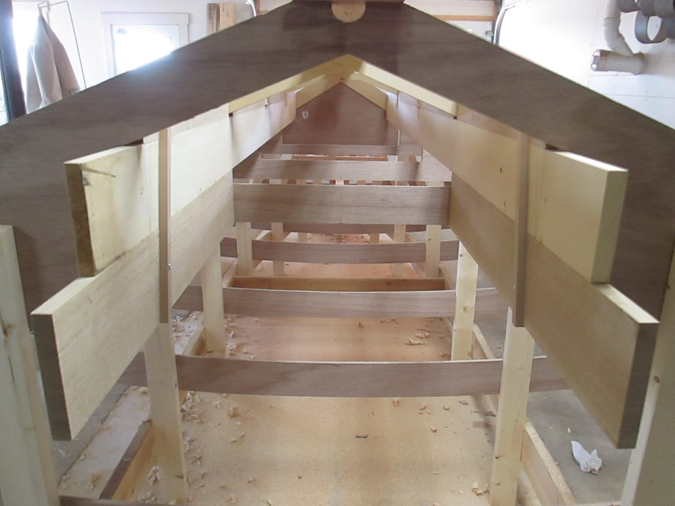
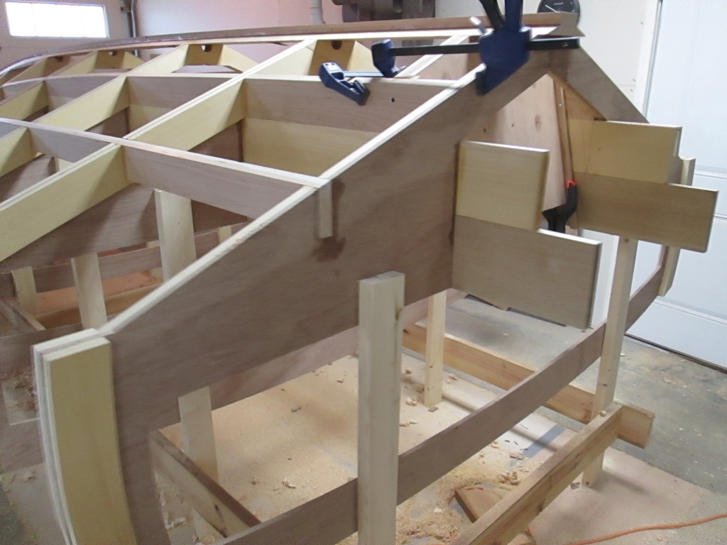
So, enough of the class room education. The easy part of the fairing preparation for most of the hull is now done, and it’s time to get moving on the front. Sooner or later, you gotta get off the couch and put the ideas in action.

I am quite curious how this is going to turn out!

The Chine Line / Scarf Joint

The line where the bottom of the boat meets the side is called the chine. For slow moving, displacement boats, that area is rounded for the most efficient travel. But, for speed boats like the one I am building, the motor is strong enough to push the boat up onto a plane.

Edges created by a sharp chine on the sides and cutoff at the transom, lets the water separate cleanly from the boat, reducing the wetted surface. This loss of frictional resistance allows planing boats to reach amazing speeds.

When the chine line is defined, it is partly visible when the boat is at rest, and more fully shown at planing speed. It becomes an important part of the visual profile.

That edge must be strong also, because the corners are where the boat may contact a dock or an object in the water. For my boat, I am using one inch thick Cherry wood to make the chine log, as it is sometimes called.

The trouble is that the boat is 20′ long and my longest cherry is 12′ long. This requires joining two pieces using a scarf joint. Below are shown cutoffs from free hand cutting the roughly one foot angled ends.

The ends are not a perfectly consistent angle, so they are sanded, using a backer support to keep them from bending.

Then, the sides were matched together and assembled with two screws to prevent sliding under glue and clamp pressure.

Below is one 22 foot chine log clamped together.

Now they are ready for glue clean up and assembly onto the boat.

The chine log dimensions were picked specifically so it could be bent on a comfortable, easy curve from front to back. This is intentionally done without steam bending which is cumbersome and can give irregular results.

When the scarf joint is well done, and the grain of the both pieces are selected for longitudinal grain, without knots, the log will bend very consistently. As it is temporarily clamped in place, it helps to show where to adjust the cross frames on the way to creating a fair and beautiful curve.

Boat Building Tools

Woodworking is woodworking, unless you are building a boat. For a piece of furniture, most of the parts are pre-cut on heavy stationary machines, jointed, planed, doweled, mortised, or otherwise shaped and sanded before assembling into the final product.

Not so, on a boat. Many parts have to be attached to the boat first in rough form, and then have final shaping, sanding, notching, etc. done in place. Great furniture respects hand work also, but it becomes essential when messing with a boat that gets heavier to move every day.

Becoming adept with hand tools is like anything else. ” Necessity is the mother of invention,” and “practice makes perfect.” The first on the list is the hand saw, but not like the saw I used to build the tree house behind my house on Myers Avenue near Concord Junior High School. That saw was already old and rusty when I got started on the job. I think it took me half a day to saw twelve feet of 2 x 6 floor boards straight on the end.

One of the main problems is that wood saws are so difficult to sharpen, so many saws hanging around home shops are usually not much fun or good for anything.

Ah, but this saw is a Japanese pull stroke saw notching for a runner. The brand is Irwin, and it came from Lowe’s but was either made in Japan or very well imitated. Pulling to cut allows a thinner blade, less effort, and more precision. The motion only takes a little while to get the feel of it, and it is a satisfying effort.

Next, are some work horses of the boat work, the scraper and rasps. The two handled scraper does a great job with glue or epoxy that sqeezed out and hardened. The replaceable carbide blade allows it to be renewably sharp and the two handles give a tremendous focused power. The rasps are good for rounding edges, and rough wood reshaping. I have blue tape on one end for hand holding comfort, but also to make sure it is not doing harm where it should not cut.

On the finer side of reshaping, and especially for making a curve regular, or fair, the home made long board is the champ. The 1/2″ plywood is flexible enough to follow a mildly curved surface, so when you are done, your hand can slide across the surface and say all is well. The handles help to work with pressure, more comfortably. The size is made to use a portable sander belt, opened up and contact glued to the board. This is not fast work, but an amazing ability to take out dips and rises on a long curve.

Up next is my wood mallet which is also home made. It is helpful to have a large contact surface, so I can concentrate my eyes on the chisel working, and not get my thumb hammered. In this case, it is also carved specifically to fit my left hand, which you would feel by picking it up and finding its fit.

The chisel is from a set of Iyoroi Japanese chisels. They have perfected metallurgy for hand tools. This blade has a thin lamination of a very hard cutting edge fused to a more ductile metal which helps not to break so easily. They are expensive, but they sharpen very well, they have been a joy to use for nearly thirty years.

In the chisel drawer below on the right are the four chisels I use the most for all kinds of normal chisel work. The middle three are specially made for cutting mortises, and the next three are old Craftsman chisels. They don’t keep an edge so well, but are sure good to dig out drywall or old linoleum. I also don’t worry so much about hitting a nail, or dirt.

The one on the very left is actually a 1/2″ chisel, old and nearly useless. That is, unless you love an old chisel just dull enough not to scrape off the drying glue without damaging the wood. It is almost always laying out on the bench somewhere, ready to help.

Below are some more favorites, my Lie Nielson collection. From left are: Scrub Plane, No. 4 Smooth Plane, Low Angle Bench Plane, Scraper Plane, Block Plane.

The dust tells the story if which planes are getting the most use at this stage of the building process, although my wife just thinks I make generally too much dust. The low angle plane has been the biggest help straightening and fairing the runners and frames. The pile of shavings are a pleasure each time.

The beauty of the shavings all over the floor makes it easy to push off clean up to another day.

Wooden Boat Transom

The transom leads the pack of all of the engineering challenges presented in boat building. In my case, it will need to be strong enough to hold the weight of a 500 plus pound outboard motor, with all of the rotational forces of acceleration and turning. Last, but not least, the transom will need to stay intact in the bounce of choppy water, and the serious bumps from road pot holes and railroad crossings.

The keel stem and long boards are looking strong enough to bear up to normal water pressure forces and the forward pressure from the motor. Next, in order to model where the transom would go, I cut a pattern out of cardboard to visually evaluate the best place. The tip approximates the mounting angle for an outboard motor.

I picked a location inside the first cross frame and screwed a slat at the recommended 13 degree angle to act as a guide for the router. Then, I routed a 3/16″ deep groove, 3/4″ wide for the end blocks on both sides. Much greater strength is gained with a cross grain stop.

Here are the stop blocks in place, and a temporary view through the sub floor transom and fuel tank space.

The transom was laminated from four pieces of 1/2″ marine plywood with epoxy. One more 1/2″ ply will be added to make a strong motor mount plate.

Once the transom blank was adjusted to fit the keel, and inside the runners, it was epoxied in place, against the cross stops.

Below, the keel has been cut shorter, and the first frame partly cut out to reveal the motor mount area. The scrap pieces are temporarily used on the transom help to spread pressure evenly as the fifth and last lamination is epoxied in place.

The rest of the stern will be built out when the boat is turned over, adding more transom support structure, but that’s for another day.