The Art of Persuasion

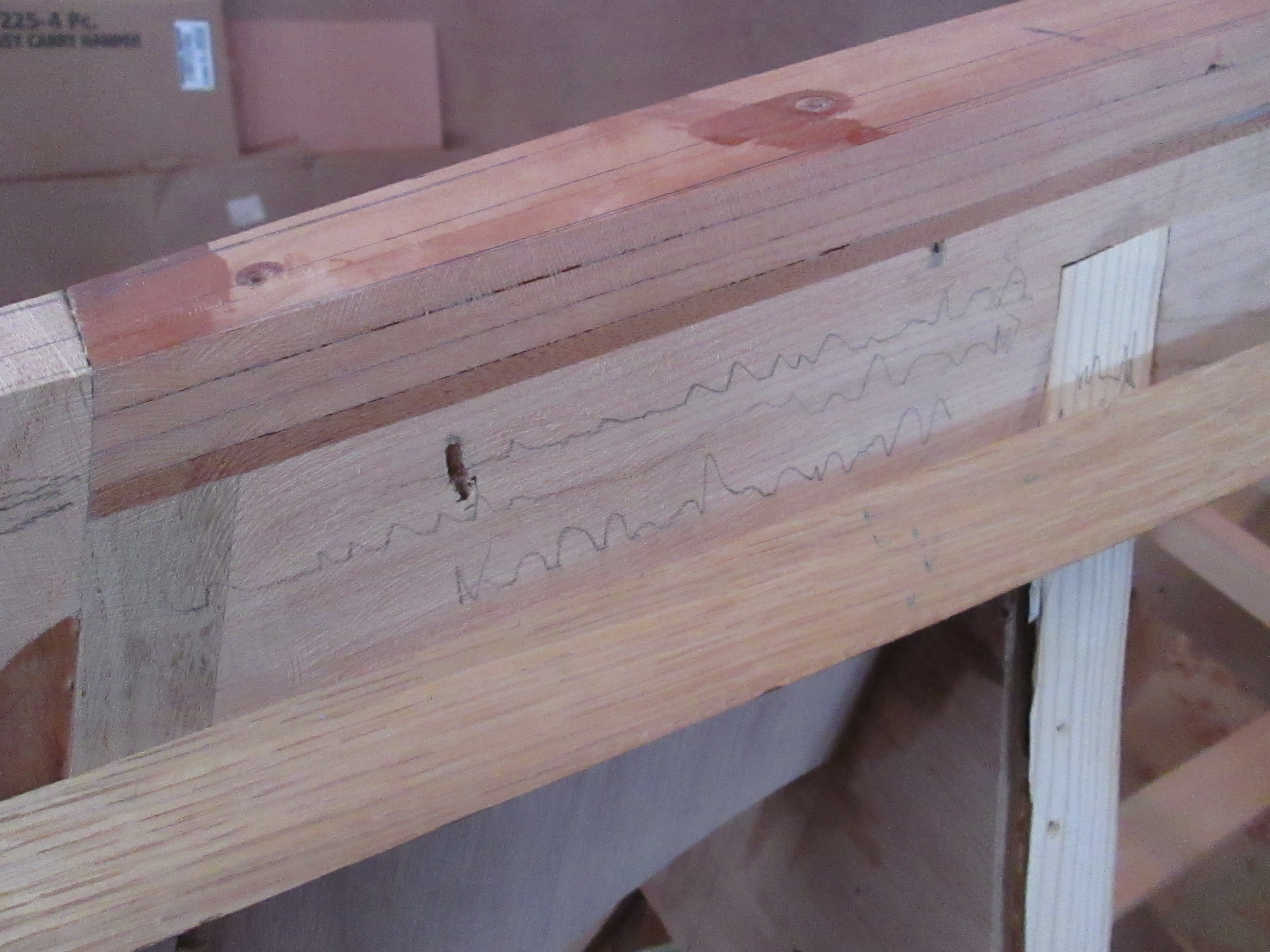
Jan’s Grandma used to say “A man convinced against his will, is of the same opinion still.” I guess that could apply to a dog also, like Buck who would sit at the end of his chain beside the electric fence, as his head bobbed every current pulse. Sometimes, even a board has an “opinion,” with internal forces that show themselves when it is cut, springing apart or pinching together.

So when building furniture, parts are cut slightly over size, to discover any internal stress causing bend or twist. Then the edges can be straightened and the twist removed, before assembling it into the piece of furniture.

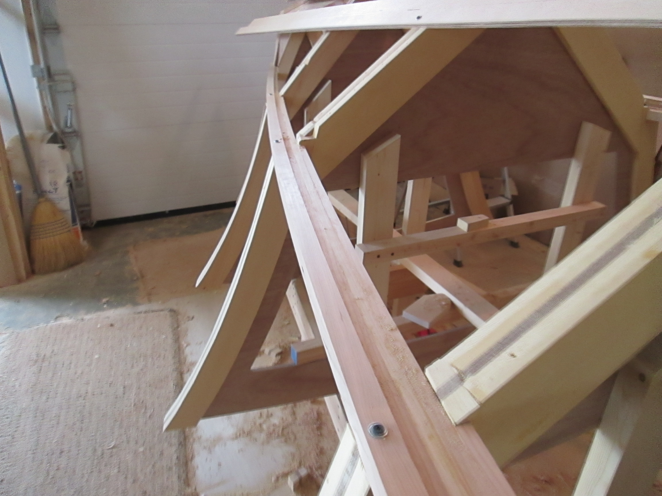
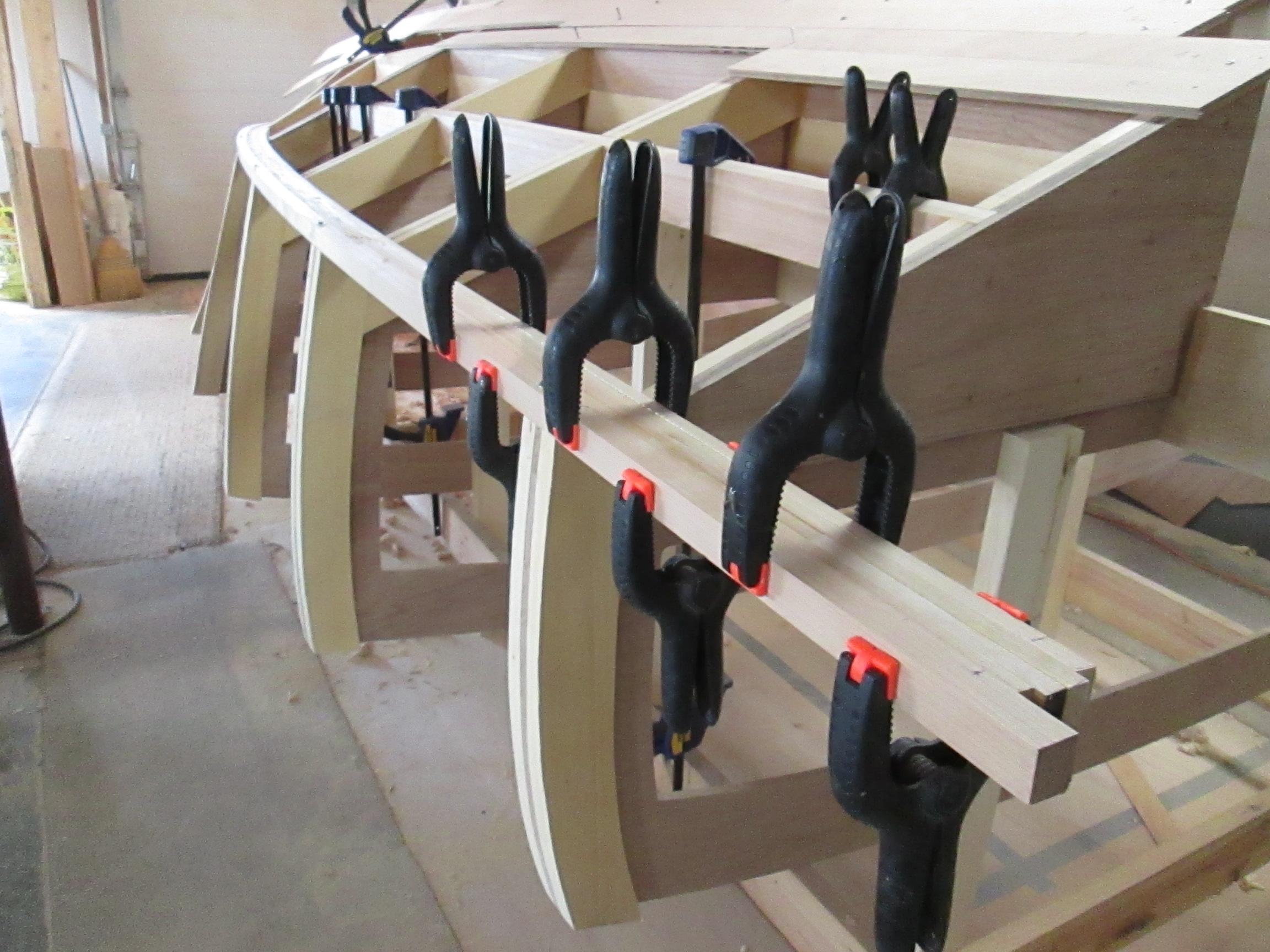
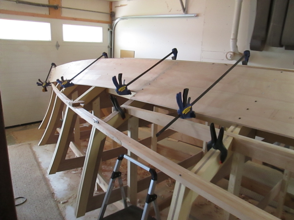
Boats, however, have so many curves that require different techniques to build and assemble. Laminating a straight piece to the curved chine stringer requires a bunch of clamps to persuade it to lay smoothly against the others.

Another example is in the machining of the tongue and groove planks. It is dangerous to have hands pushing small, thin parts near the cutter head. These angled feather boards are clamped with pressure downward, and inward against the feed stock, to allow hands farther away from the danger zone.

In the case below, the two ends of planks did not want to lay flat and made it difficult to fit the next piece. As the screw block is tightened up, it forces the edges together and the next grooved board will fit and hold them flat.

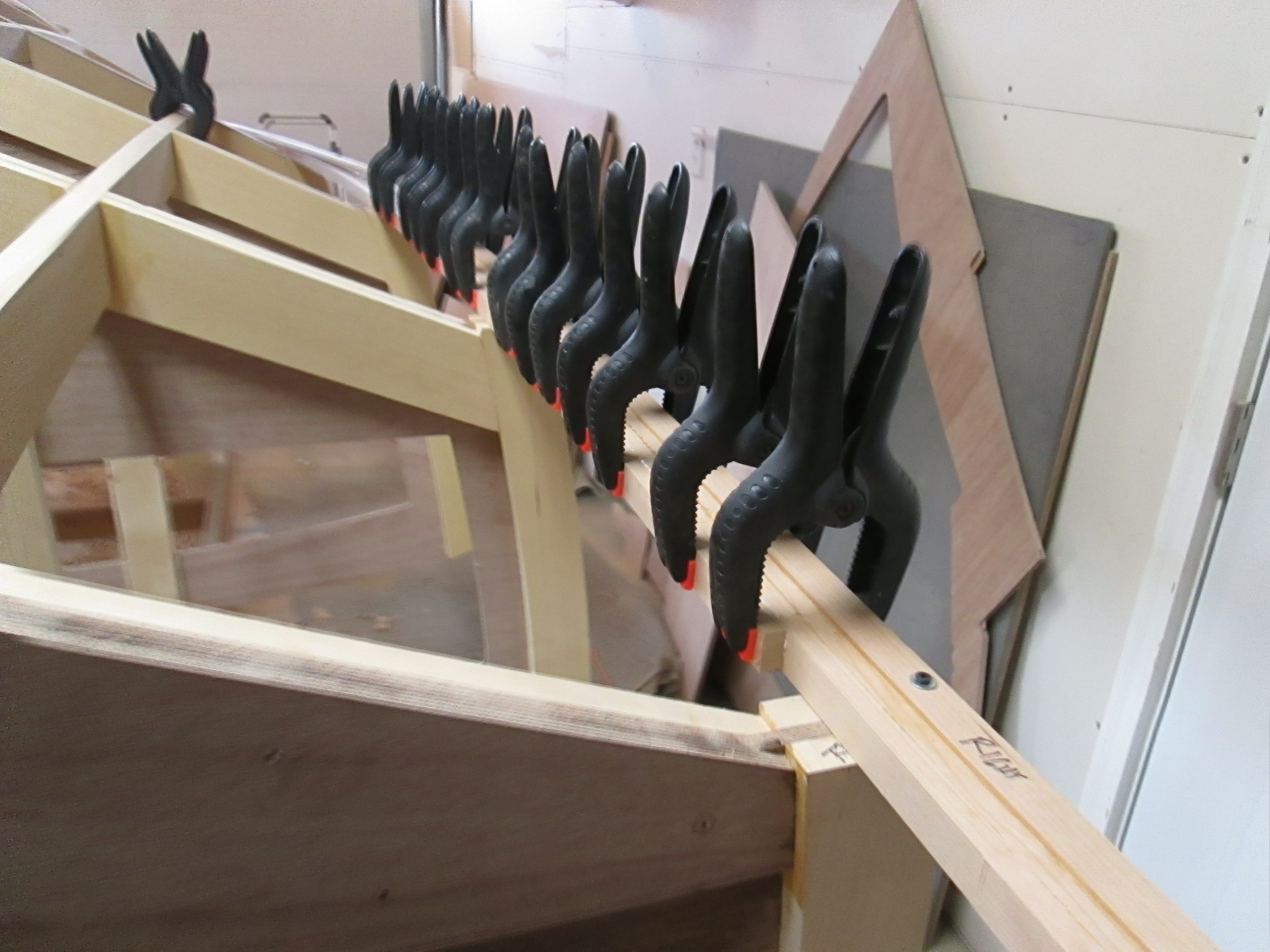
As the hull planks are assembled, some clamp pressure is needed to conform to the curves of the frame work.

Below, the angle block is shown which was temporarily screwed to the frame to hold the clamp securely. When the final assembly with epoxy was done, the clamp was replaced by screws to hold the planks in place.

Assembling the second side needed another temporary block to hold the clamp, and screws hold it together as the epoxy cures.

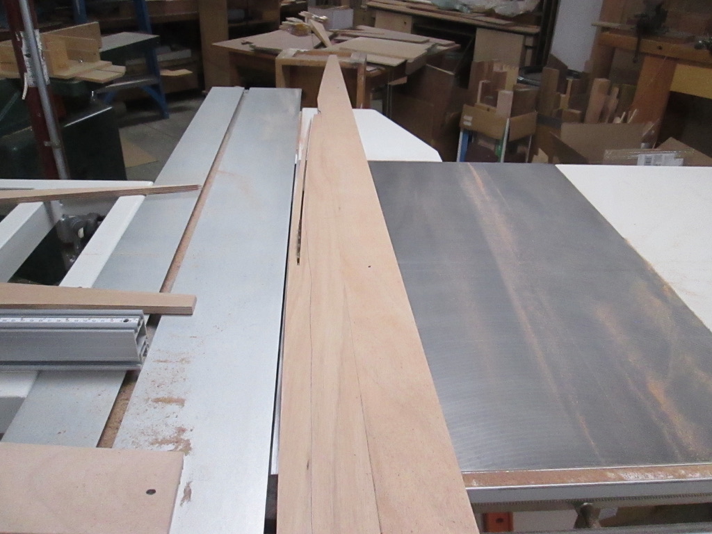
Where the planks come down meet the chine rail, the fit is more difficult. For a long curve, the cut can be done on the table saw to make an over sized plank.. It is a bit dangerous, but slow, steady cutting with gentle side pressure produces a good starter piece.

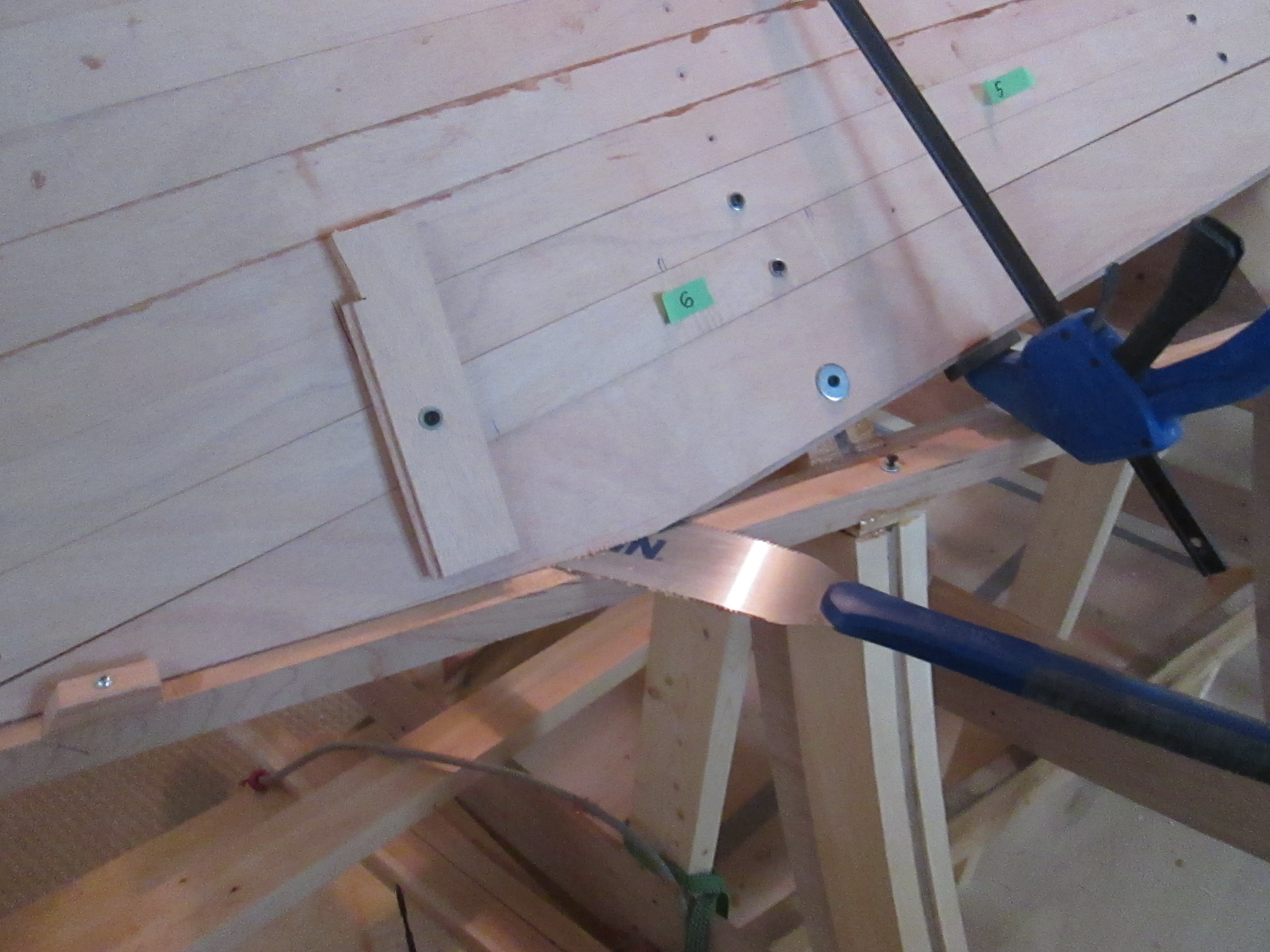
Below, the bottom plank was angled out too much, so the saw was used to cut through the contact point, so the wood block could push the bottom part inward. The clamp and screw with a large washer are used to hold it solid when the epoxy is added.

Temporary hammer blocks help to press another bottom piece in place, testing the fit. As it meets resistance, I mark the contact spot and continue sanding or cutting the high spots away.

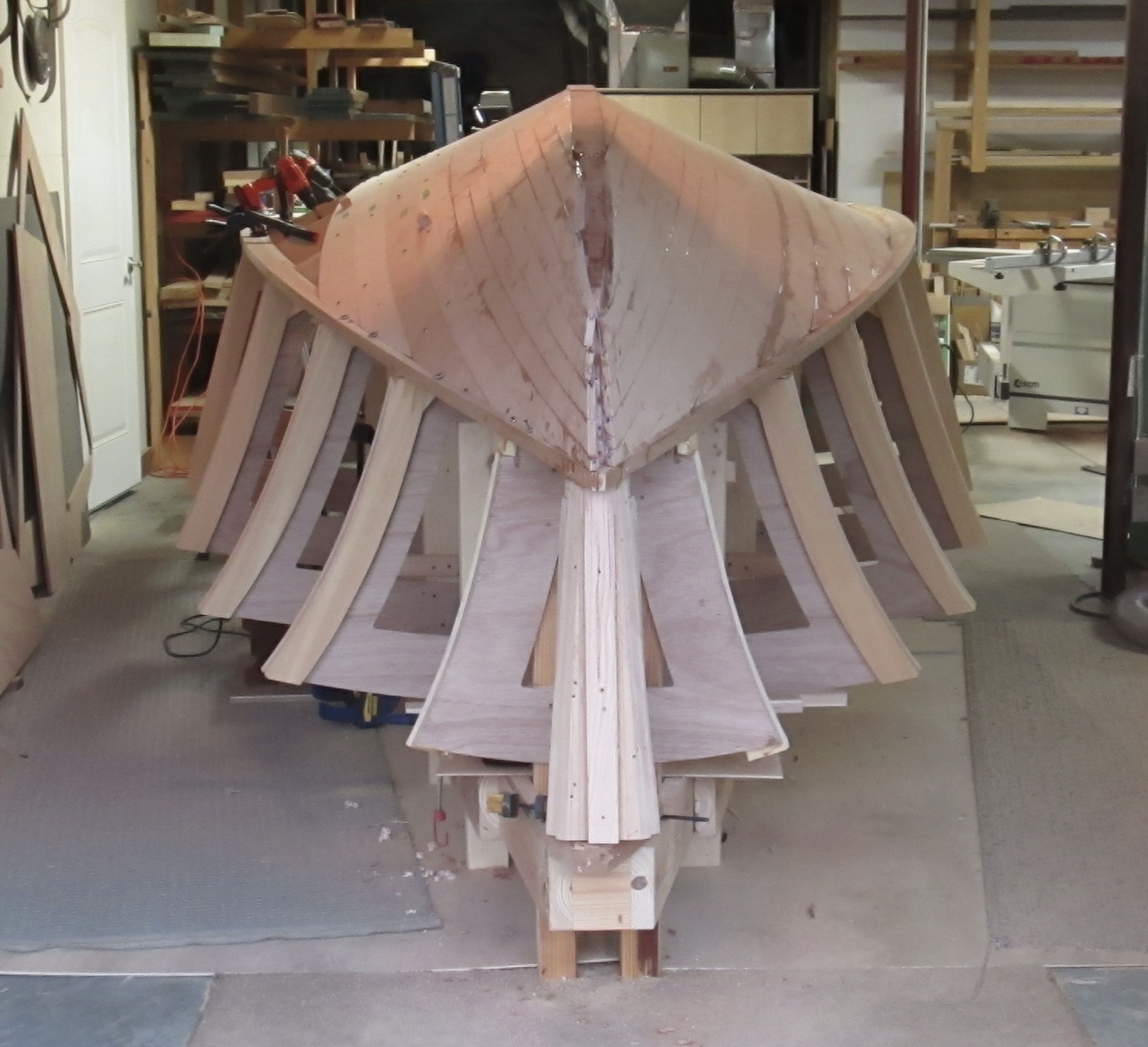
At the end of many trial attempts, eventually the plank can be hammered by the “Persuader” fully into place with the plank fitting well to the rail. The pieces marked with green tape show which ones still need to be removed and epoxied.

Finally, only a few planks remain to be fitted on the second side. It breathes a sigh of relief, nearing the end of a great step of progress.

Next up, some fairing, a second layer of thinner plywood, and paint before turning the boat over for phase two!

Installing Hull Planks

Next up to light some fire under my feet is none other than the third member of the previously mentioned Car, Boat and General Design Club. At church, between services, near the offering box, where we regularly have our scheduled meetings, Bob Herrold asked me what my time schedule was for the boat to hit water. I said that I was optimistic for a spring of 2025, which gives me two years from today.

That seemed unacceptable to Bob as he had a disappointed expression on his face. He said that it must be a pretty complicated boat! True, but with other life complications. I need to work as hard as Bob does in his volunteer work at the hospital.

Consider it a challenge taken, and I am determined to shift into a higher gear. The cross frames are mounted, and the keel and structural beams are connected to the transom. The chine is now complete, and all surface parts have been faired.

The time has arrived to put the hull planks on the bottom of the boat.

Below is shown how the tongue and groove planks machined on my router tables from 1/2″ Marine Grade Plywood fit together.

The large washers for the screws are needed to hold the front planks to the keel frame. The extra length will be cut away later in the fun stage of final shaping.

The most difficult parts are the border planks which must be shaped to fit to the keel or the chine. When they don’t line up side by side, I sometimes use a guide block as shown below to pull out a depressed area. Getting a great fit to the chine is a challenge also, and when it is close, sawing through the joint is a good way of reducing the high spots.

When dry assembly is done, the hull planks are numbered, removed, glued with epoxy, clamped, and screwed to the frame members.

The epoxy takes a few hours to set up, but I generally wait over night to make sure it is hard. Then all of the screws are taken out, because any metal left in a potentially wet environment will corrode and the wood around it will eventually rot.

The surface created is already pretty well shaped, due to the benefit of the tongue and groove method of joining pieces. Sometimes, as shown above, an alignment block helps to flatten a poorly cooperating board.

After this layer is glued on, a thorough sanding will be done to “fair” it smooth without high or low areas, only regular curves. Then, the half inch bottom plywood will be covered by a second layer of 1/4″ plywood, making a strong and stiff 3/4″ bottom surface.

Boat building is a long, demanding process, so dividing it into smaller steps helps to see progress. This step of seeing the structure begin to take shape is a strong, motivating milestone.

Another encouragement comes from other boat builders. We are few and far between, so we don’t tend to have much routine contact. However, in the history of building both my boats so far, curious people from 140 countries of the world have checked in. Thanks to recent readers from Belgium and Ecuador. I hope your boats are coming along spendidly.

Stiffening the Chine

The pretty curve of the chine previously shown was made from a two piece assembly of 1″ x 1″ cherry, which was the maximum thickness to make the bend comfortably. After the outside shape was established, I added 1/2″ laminations to the inside of the curve.

I have about 20 small spring clamps, and 20 more larger ones for a task just like this. I love my wood screw clamps, my pipe clamps and some miscellaneous hand squeeze clamps, but more often than not, I reach for these useful spring clamps.

Once the curve was established, the 1/2″ layers easily fit to the curve and began adding great strength. As shown below, two laminations started from the front and at each cross frame, another layer was added until five were in place. Since this assembly was edge to edge long grain, I used Titebond III, but from here on, most of the connections will need to be structural strong. That will take Epoxy.

This becomes the chine line, and the future spray flat.

Encouragement continues to drift in: We recently went to a graduation open house for Keegan New, whose family lives on a small farm of mixed metaphors. On one hand is the car barn which reflects their family’s love for old cars, and fixing them up. Grandpa New got it started with his restored Dodge Charger and interest in the classics. Among the grandchildren, there is a restored old VW van, a Dodge Dart, and a couple other Mopar cars in progress.

The other barn is more along the lines of a typical 4H family, and Keegan took Jan and I there, with particular pride in some sheep he was raising to show at the fair.

This sheep is named “Jan,” and Keegan mentioned she should compete successfully, with the well developed hind quarters.

The next two sheep appear some what embarrassed when the person they are named after: “Doc” and “Lehman” actually shows up to say hello.

I think Andy Warhol said that everyone gets fifteen minutes of fame. This coming September at the Cass County Fair, I look forward to getting a generous lifetime dose.

Shaping the Bow Line

As usually happens with detours, you don’t see them coming. That is the problem with big ideas, it is hard to know in advance where the next bottle neck will get the progress slowed to a trickle.

Once awhile back, I heard that if you don’t know what to do next, clean the shop. I did that, not perfectly, because a boat just collects debris, but it did prevent making a mistake to compound the problem. The next applicable advice goes along the lines that “a journey of a thousand miles, starts with the first step.”

The problem of so much bend and twist required in the surface change near the front of the boat had me stuck. So, I started a “first step” experiment by cutting my typical 4″ hull planks into half, to see if they could be clamp and screwed through the angular bends required. It did show me that the 2″ widths of the 1/2″ marine plywood could be forced to fit. Had this not worked, I would probably have tried using a 1″ strip building method.

The next challenge, and the most important was how to make it look good. The best shapes that I observed were only concave in one direction. Even though there will be an up and down concavity, all of the lines going front to back can have a slight outward curve, as shown above. In other words, a bowl shaped depression at the corner is not a functional or visual strength.

To attack this problem, I prepared a 10′ long, straight grain white oak stringer, about 3/8″ by 1-1/2.” This was attached by one screw at the distant cross frame, so it could be moved up and down at the front. As shown below, I was pencil marking the high spots as the long fairing guide moved down.

Then, it took some judicious grinding by this trusty Craftsman body grinder with 36 grit heavy duty sand paper. This is not a tool for the faint of heart, or the imprudent craftsman. It took a fair bit of practice, but eventually it was tamed as I understood the nuance of a gentle touch with the proper angle of action.

After multiple pencil marks and careful grinding of the high spots, I arrived at the surface below. In most cases I was cutting wood away, but the light colored filler stick was glued to the first frame where it was low. After working the top area, the fairing stick was unscrewed at the distant axis, and repositioned about 5-6″ down, only to repeat the process for the next zone down.

It feels like the right direction, but confirmation will only come as the shell is installed.

Meanwhile, some encouragement continues to trickle in: Bob Cross asked about when it would be done and how many hours a week I work on the boat. My answer was two more years and I average about 15 yours a week.

This is mainly due to the vacuum of time gained from retirement, getting filled by even more time consuming activities in the near and far reaches of the world. Bob said, “If you worked more hours a week, maybe you could get it done sooner.” That deserves a serious consideration . . .

Final Fairing

When the cross frames have been mounted on the strong back, the longitudinal center support beams are installed, and the transom is firmly connected to them to resist 3D forces, we are ready to move on. The next step is preparing the wood edges that contact the shell so when I add the hull planks over them, they will lay in the most fair curves.

Below I am getting some help from Owen, Jane and Will, my grandchildren.

Fairing means making a curve regular so that no noticeable dips or bulges are present. I start with the tape measure to try to get both sides of the boat symmetrical. But sooner or later, it becomes an exercise in hand and eye work. Long straight edges are helpful near the back of the hull, as there is a 6-8 feet flat zone on both sides of the keel.

However, as the runners go forward, they need to follow the curve of the hull, and a straight grained bendable stick helps find the high spots to work down. Ultimately, the eye gives the final inspection and Jane and Owen appear to be satisfied.

The further we go toward the front, the more critical and difficult the fairing becomes, to see how the planks will lay on the compound curves. Below, Jeff Margush, my main partner in design crime, is working multiple test sticks close together, to sleuth out how this difficult front end can get fair and fine.

Someone should have told me how difficult it is to design and build a vertical bow shape. Much chair time for thinking and some couch time for dreaming is required . . .