Intuitive Wooden Boat Engineering

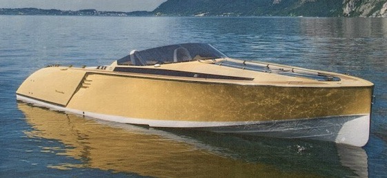
Boat strength is an imperative topic in the creation of a boat, designed to safely carry people. If you want the full story in mathematical detail, Dave Gerr wrote a book called The Elements of Boat Strength for Builders, Designers, and Owners. You could call him “Noah Thing or Two.”

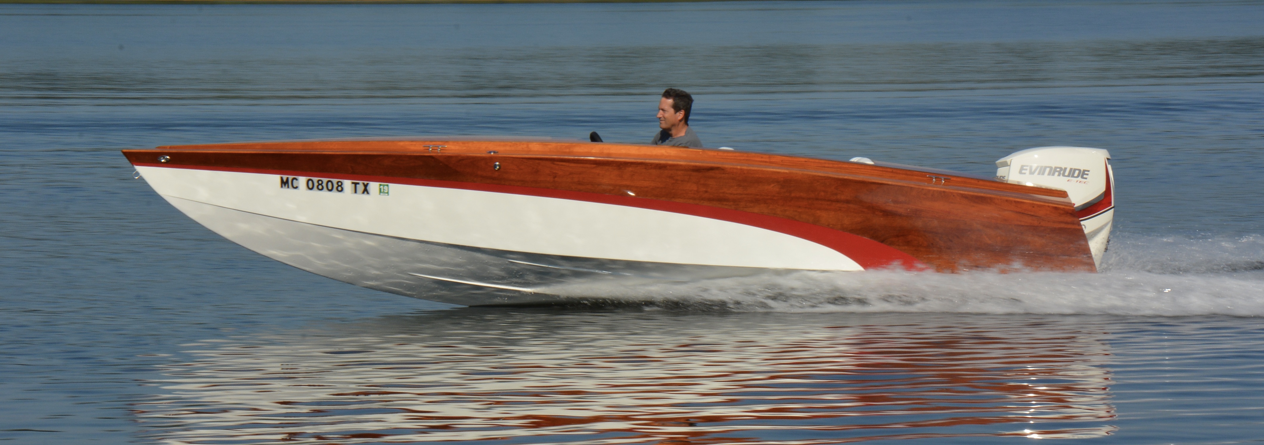
He lays out multiple graphs of plank and frame dimensions for all sizes of boats. This gave me comfort on the first boat when I planned the shell thickness of 1/2″ on the side and 3/4″ on the bottom. When I covered it inside and out with fiberglass fabric embedded in epoxy, I figured it was all good. So far it has survived lots of railroad crossings which will show up the weakest link.

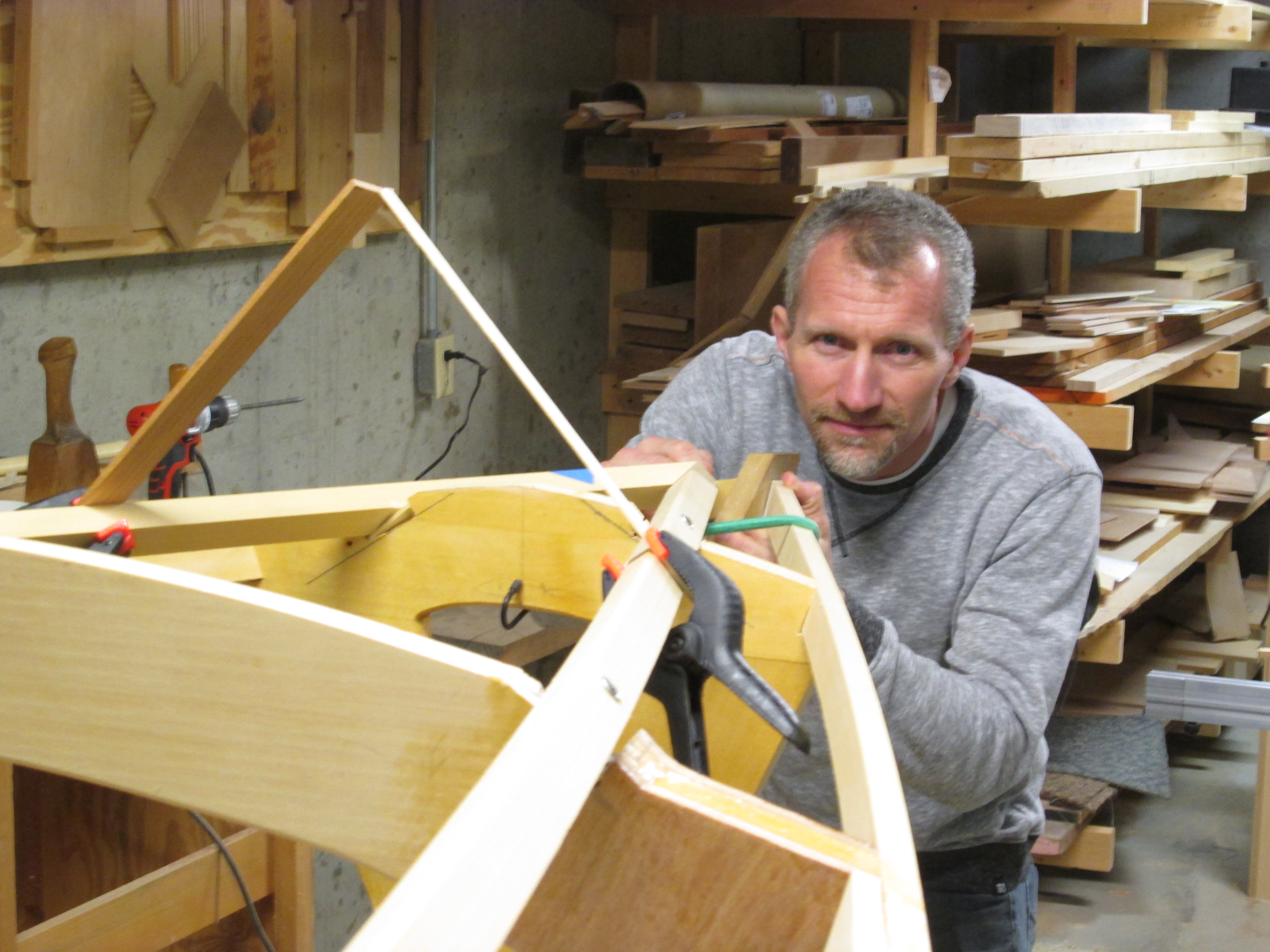
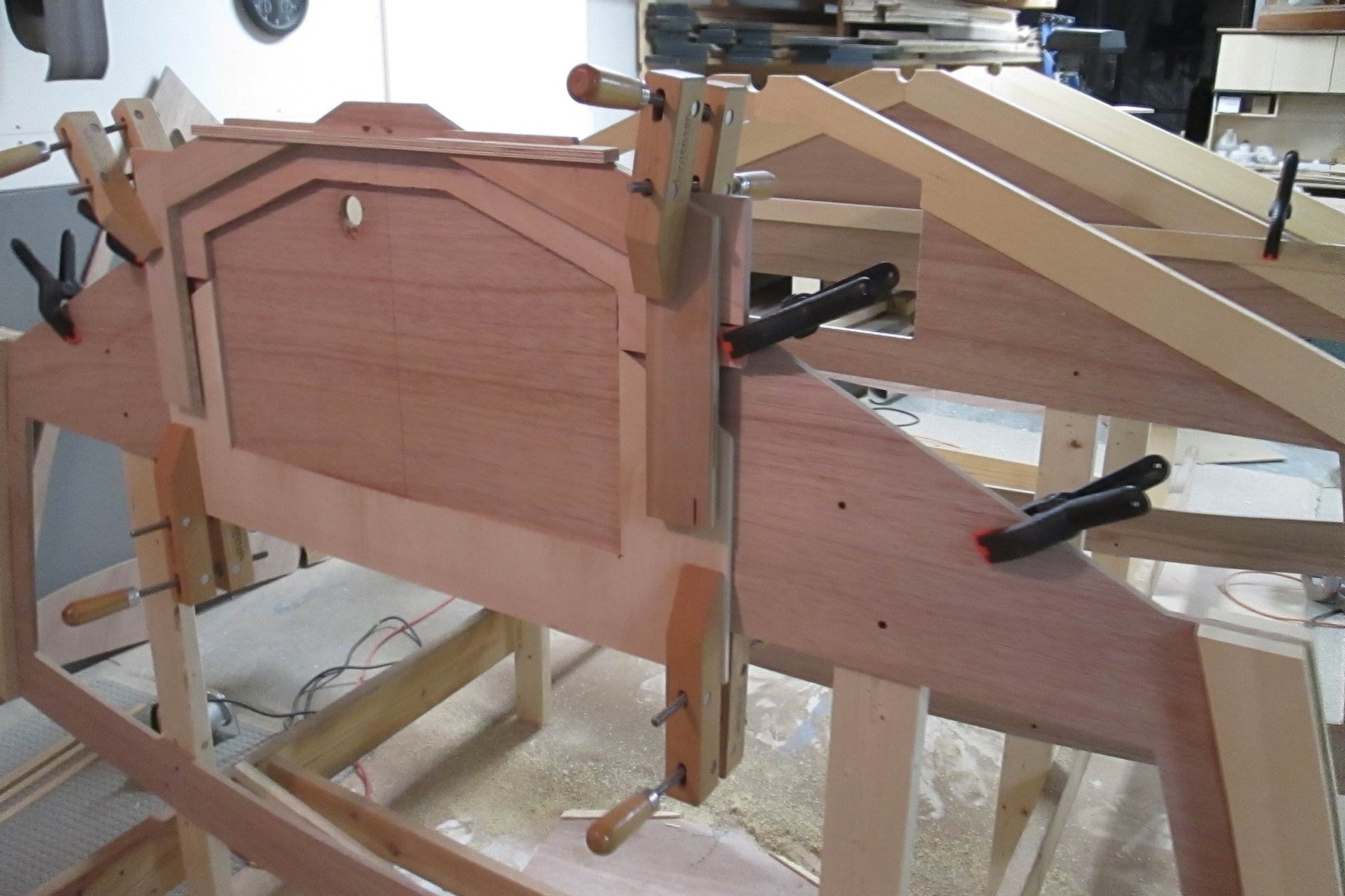
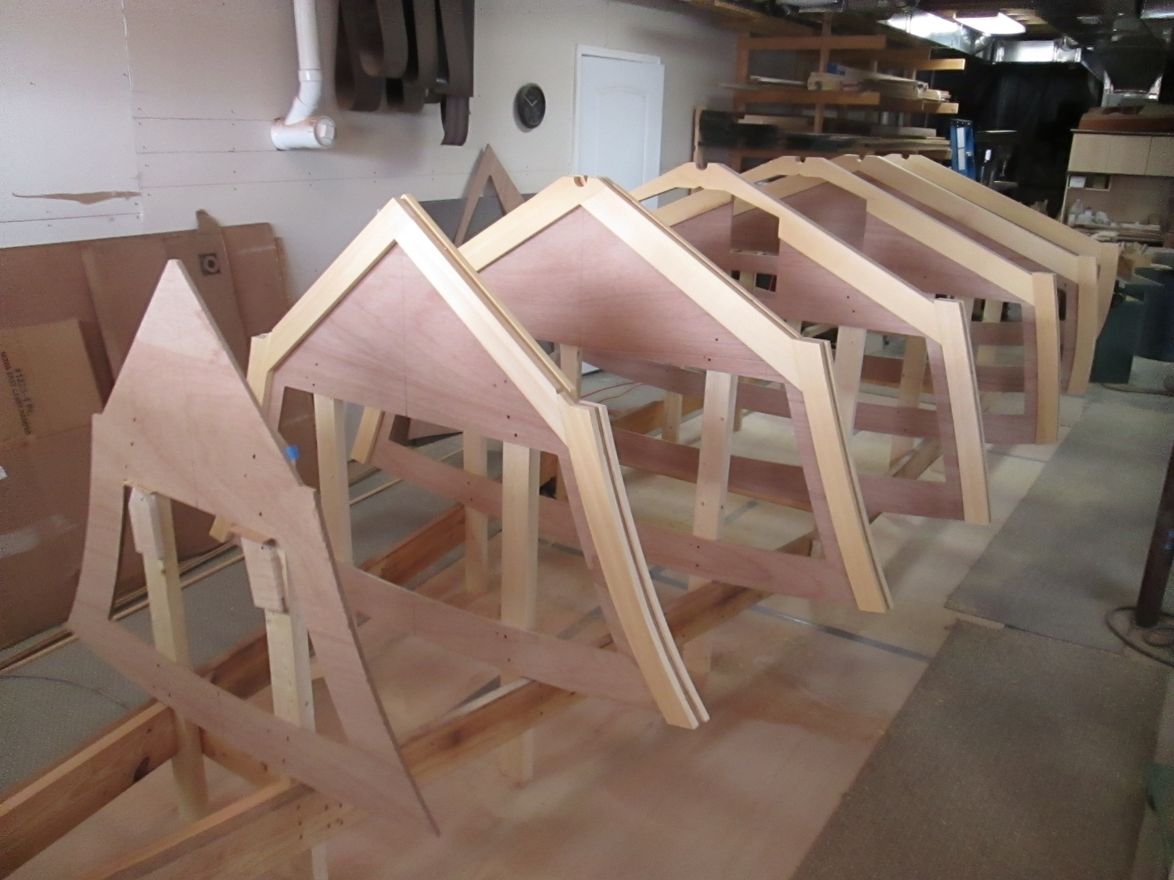
Since I started with the 1/2″ Marine plywood, CNC cut cross frames, I needed to first strengthen them.

The Alaska Yellow Cedar left over from the first boat served admirably to stiffen the edges and provide general frame strength. The deck will be reinforced after turning it over.

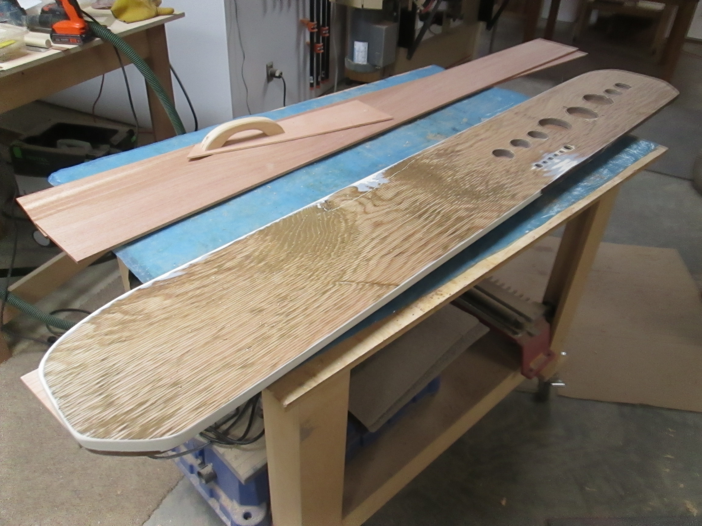
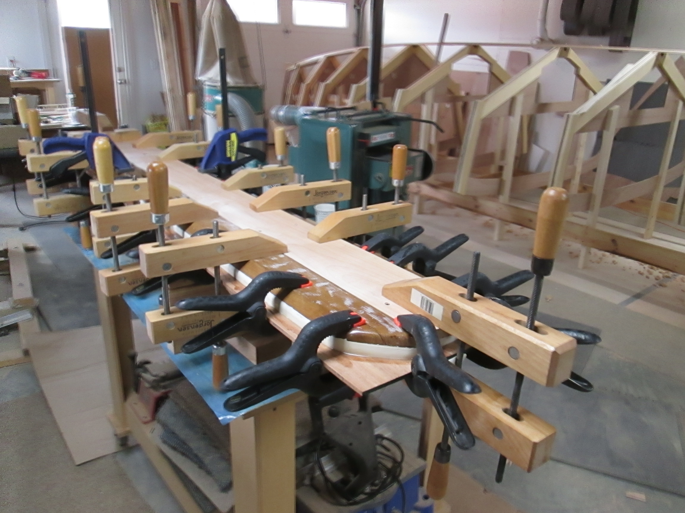
Next, the frames needed to be connected, and the keel was the first place to start. The fair curve of the line was more critical than strength at first, so I used a single piece of Cherry that was planed down just thin enough to make the bend without needing to do any steaming. Ah the beauty of the line, however weakly drawn!

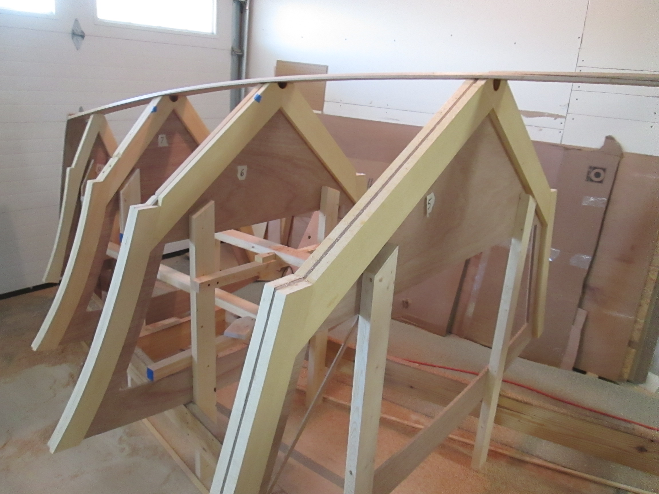
Then I added thicker wood under the long keel in proportion to what strength might be needed at each area. The boat is upside down right now, so the upper left corner of the boat is going to be the lower front of the hull when it is done.

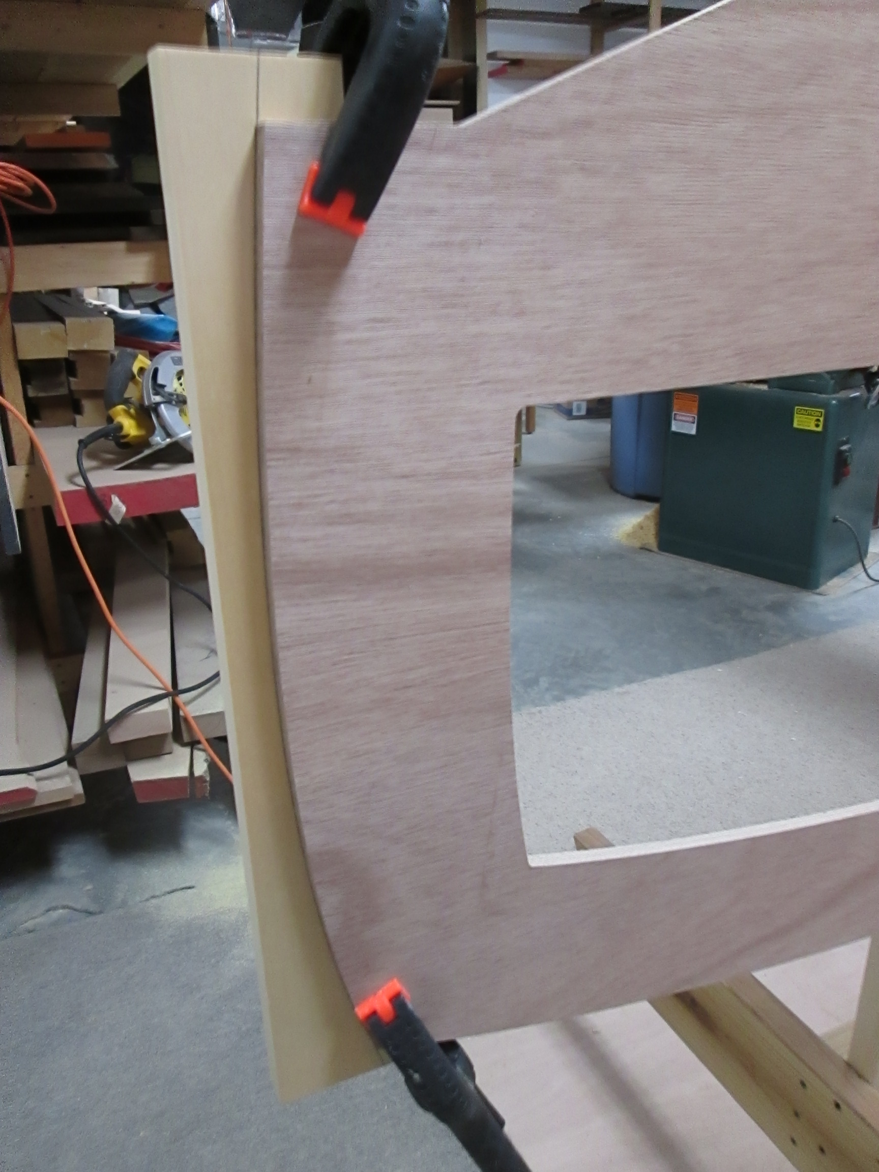
The triangle corner brace is a three piece lamination of marine plywood. Of all corners of the boat to take a hit, on a rock, the sand, a log or a dock, this is the likely place where the most damage would be done.

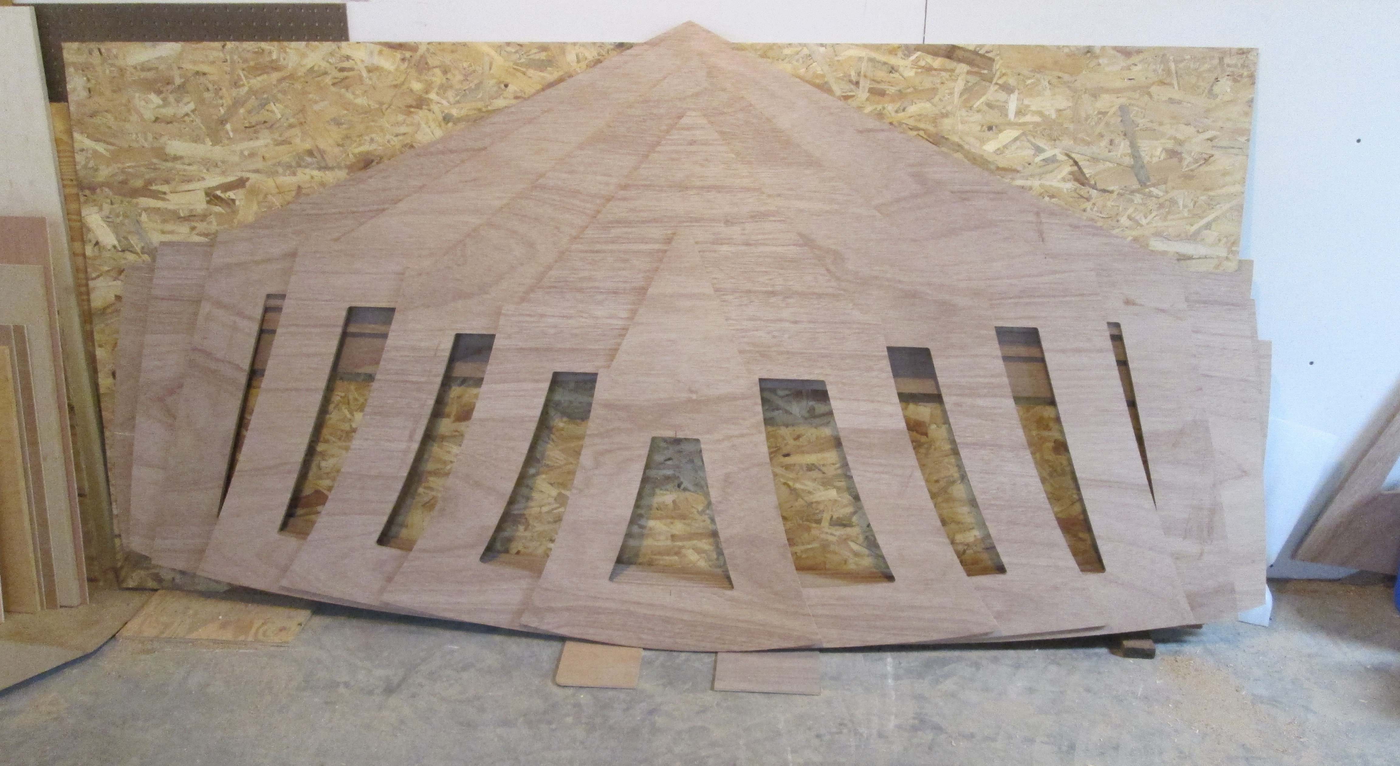
Across the top of the single board that created the keel line, I laminated a second board to give it more stiffness. The back 8 feet are straight, for consistent planing.

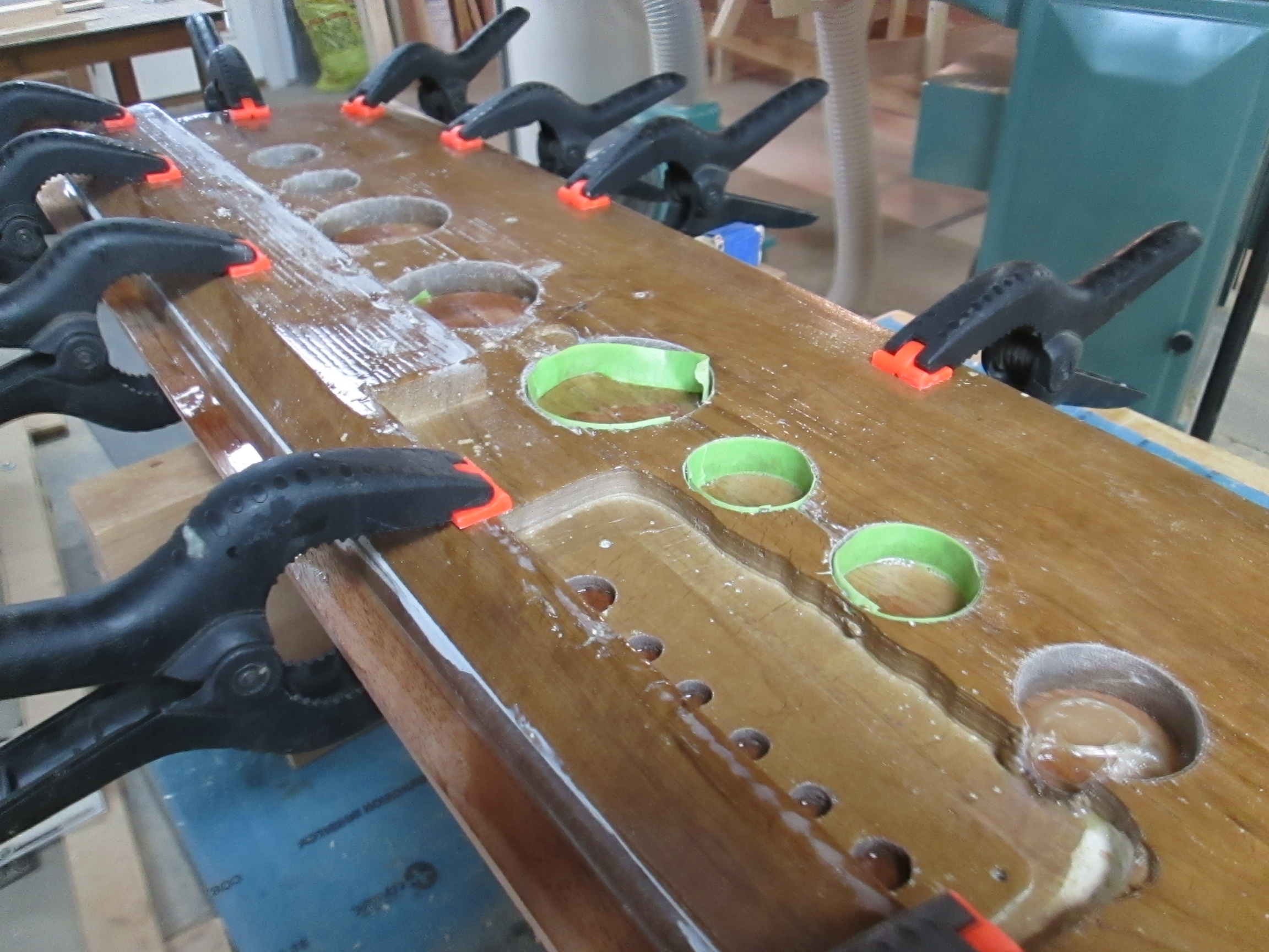
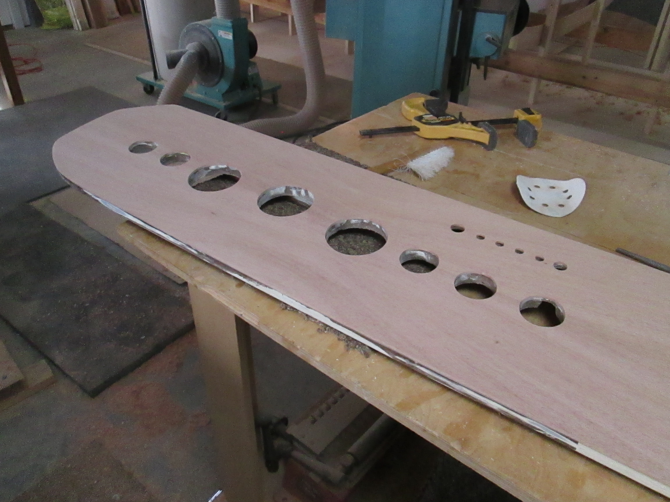
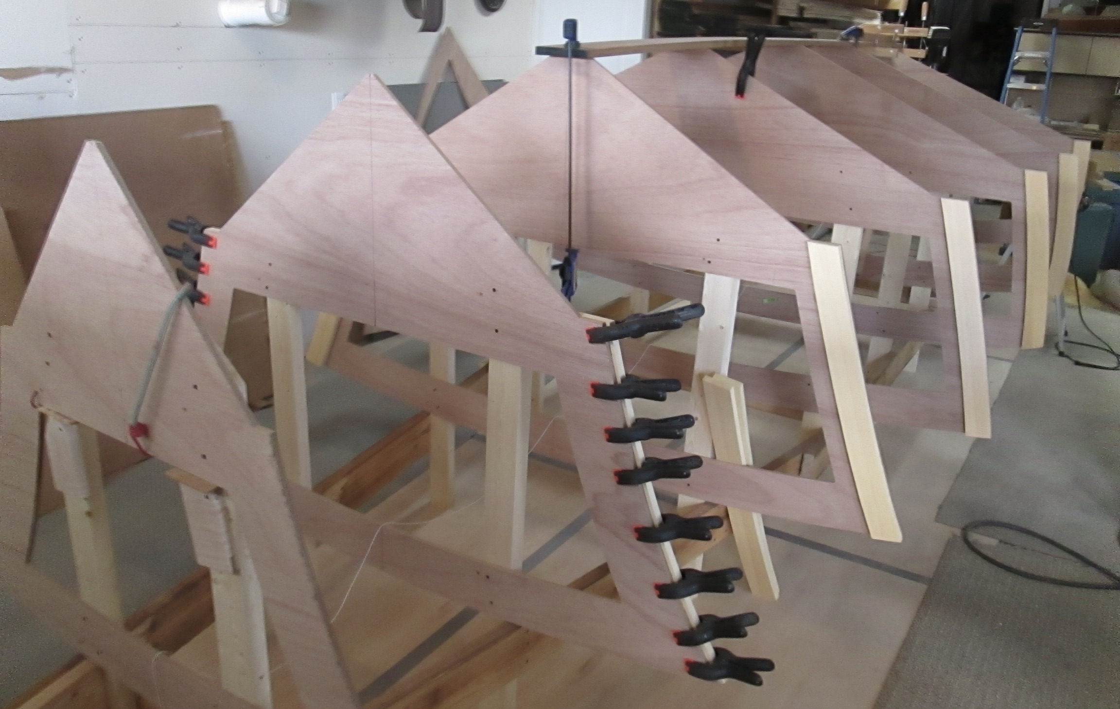
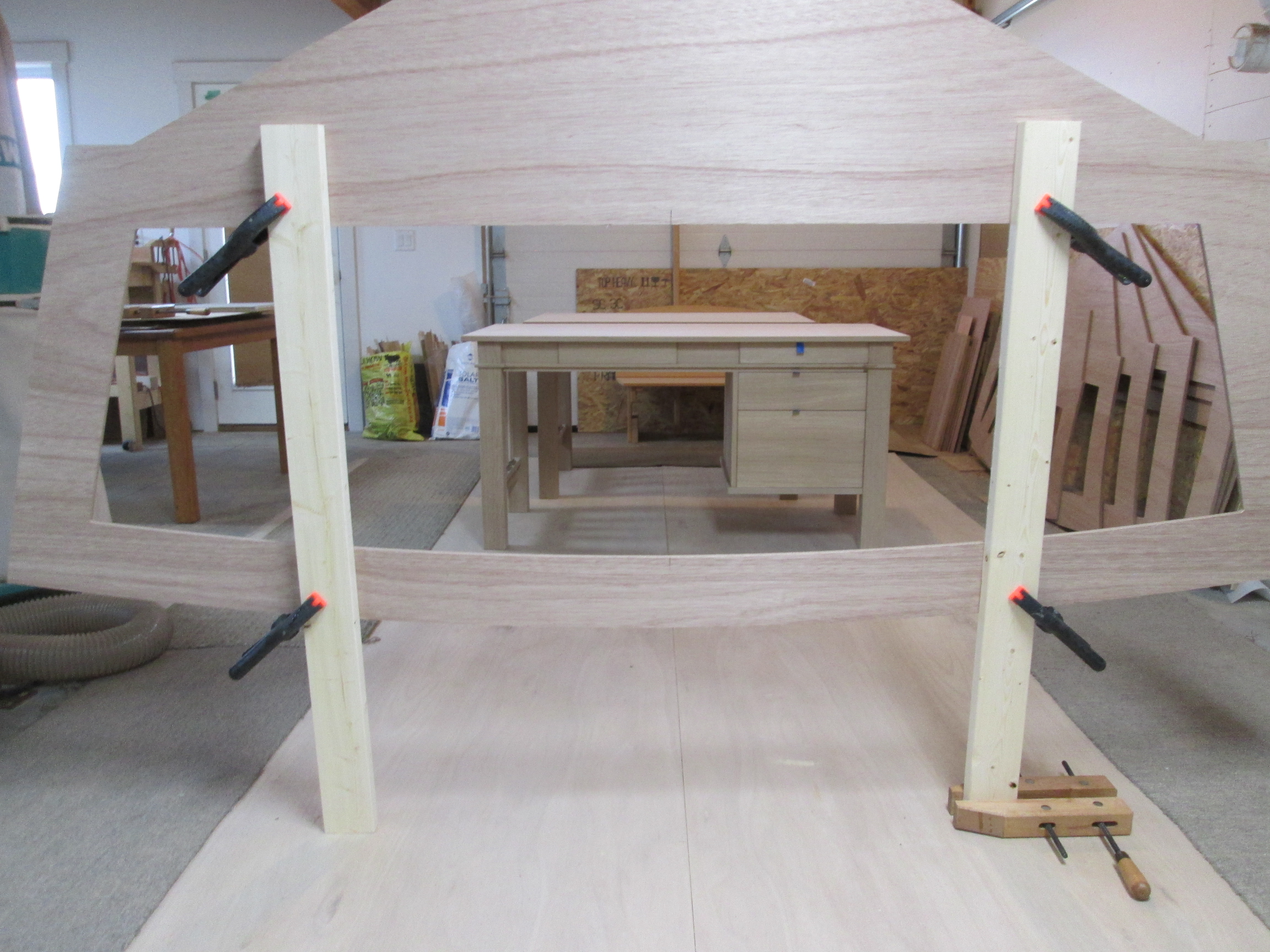
Internally, the long boards were added to tie it all together, define the space for the fuel tank, and to pass the force of the future motor to the boat as a whole.

This is a wider boat than the first one I built, and it seemed like it could use a second long runner, to help stiffen the shell. I sawed and chiseled out some notches on the frames and runners to retain the best strength on both parts.

Someday it will sit for long periods of time on a trailer. The outer runner is about where the trailer bed rail will hold it, which can deform the hull if it is not strong enough.

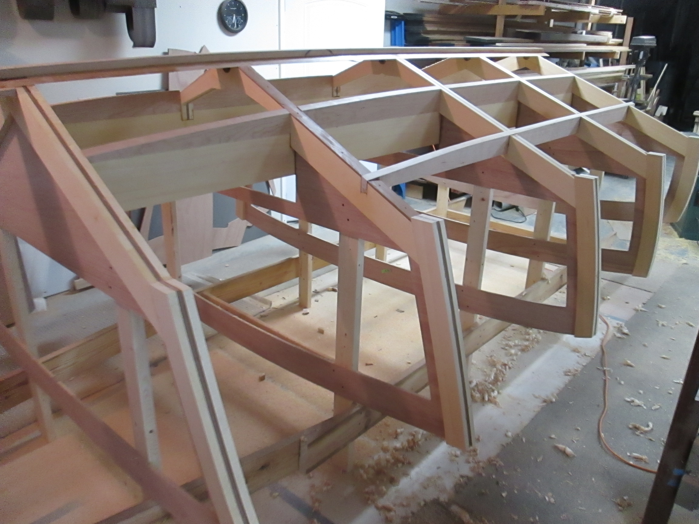
A finely curved laminated stringer at the chine line (where the bottom meets the side) will be the remaining connector before the hull planks go on . . .

The 1962 Thompson Dash Renew

The new boat is a continuing theme, but some interruptions are necessary in a 2-3 year project. The !962 Thompson being restored by Lake Effect Marina in Union, Michigan is nearing completion, but it needed a little help finishing up the dash board. Over the years it had been painted a couple of times over a plywood panel that wasn’t so special to begin with.

Scott is quite an artist with the Hydro dip technique, but getting a good looking Mahogany grain over paint never quite materialized. So he called and I went over to check out the problem. The last time I discussed how he wanted me to fix something, he said, “I have seen your boat. Just do this job like it was your own.”

That simplified the discussion, and the idea carried over to this project as well. So, the first thing I thought was that the dashboard should have the same beautiful solid thick Mahogany veneer as the transom that I rebuilt last December. (see Posts Thompson Transom 1 and 2)

I bought a nice piece of 4/4 Mahogany from Nisley’s Sons, and used my table saw and bandsaw to slice it in two book-matched pieces. Then I jointed the middle edges straight so they would lay together well, and taped them with wide masking tape.

On the back side of the dash, I cleaned and smoothed the holes for gauges and controls. Then, I taped them with green tape so there would not be much epoxy to clean up. The Mahogany veneer was left wider and thicker than the needed final dimensions to make clamping easier and to have less epoxy drip.

Many clamps were used, with wood blocks on the back side to spread the pressure more evenly over the whole surface. After epoxy bonding, I removed the green tape, cleaned up the excess, and routed the holes out to the original sizes.

Next, the veneer edge was trimmed to the original shape, final sanding was done. The dash was delivered to the marina for them to varnish, mount gauges, and install in the old Thompson speed boat..

If you having a problem with too much work to do or too many customers, you could probably fix it with a few sloppy jobs!

Otherwise, giving a “baker’s dozen” or “doing unto others how you would like it yourself,” will earn a stellar reputation.

Jeff Margush & The Keel line

I don’t remember the first time I met Jeff Margush, but it wasn’t long before the formal founding of the Car, Boat and General Design Club. We met for about 15 minutes, between first and second services at River Oaks Church, but since they did not recognize or promote the club as a ministry, it did not grow very quickly.

The fact that design was not such a popular Sunday school topic may have contributed to its slow kick off. But, maybe a decade ago, we picked up a third member, Bob Herrold, who is a strong contributor when he is not in Florida or other wise busy. We are not super magnetic, as the club is only slightly less popular than this blog.

One Sunday at a clandestine meeting right beside the offering cabinet in the lobby, I mentioned I was thinking about building a boat. Jeff said, “If you want to come over, we can sketch it up on the computer.” He listens better than most anyone and doesn’t do much horn tooting, so I didn’t know how well prepared he was to pull off the idea. Below is a collage of the kind of concept drawing he does.

I asked Jeff for some comments about line/drawing and he gave these thoughts, noting influence from his design mentor, Jim Orr:

“Design is the beginning of the thought process, the genesis of an idea. Drawing is the language of line that puts it in visual form. Generally, the first lines are drawn to create shapes that appear two dimensional. With the addition of more lines, like section lines or perspective views, form or volume can start to become visible.

Particularly when designing moving objects, these lines should be dynamic with movement and emotion. Tone or value really drive home what the form is doing, helping to communicate the design.” Here is a drawing he eventually did, summarizing most of the ideas we put into the first boat.

Below is how the first boat turned out. Did I mention Jeff also took the photo? He knows what he is doing.

Since then, I found out that he graduated from Cleveland Institute of Art with a Bachelors of Fine Art in Industrial Design. Then, he went to work at Paramount Plastics, developing interior systems for RV and specialty vehicles. Next on the journey was Newmar Corporation, where he designed exteriors and cockpits for High End Class A Motorhomes.

Most lately, he has been working on exterior and cockpit design for Tiffin Motorhomes High End Class A, C and B Rv’s. His initial concept sketches in 3d files are used to cut patterns for fiberglass tooling. If you know anything about the constant conflict between designers and the producers, there are few people who can cross that line better than Jeff Margush.

And here is an example of promotional material that he did for Tiffin:

Line is also an important element in the review of 3D shapes. Below, Jeff is checking the fairing of the sheer line on the first boat, formed where the hull side meets the deck surface.

On the hobby side, Jeff likes pretty much anything with wheels but in particular sports cars and a special passion for auto crossing his 914  Porsche. When the Porsche club needed a poster, well, Jeff managed to put out an “acceptable” design.

Meanwhile, back in the basement on the new boat, a piece of cherry wood was planed thin enough to bend comfortably on the line from the bow to the flat part of the keel at the back. When I first placed the board across the top, I had to do some adjustment of the frames until it formed a visually fair curve.

Next, I scarf-joined the bent piece to the straight piece forming the keel to the back.

The free standing cross frames of the new boat are now connected and epoxied together.

What’s in a line?

A time line, out line, red line, fine line, yellow line, dotted line, fast line, slow line. Line up, line out. Color inside the lines, walk the fine line, and find the silver lining.

Cross Frame Modification

In a perfect world, each of the cross frames would have been modified in advance, especially considering that the pieces were CNC routed and little more effort would have been needed at that time.  But, since the original computer boat profile was lost, and some guesswork needed to place the frames, it seemed better just to wait.  Setting the floor height and imagining where the fuel tank would go, for example, was easier after the frames were in place.  

The first priority was stiffening the outside of the 1/2″ Hydrotek marine plywood. Fortunately, I had some Alaska Yellow Cedar, left over from the first boat. In the last 7 years, it would have been perfect for furniture drawer sides, solid lap-joint cabinet backs and drawer bottoms, etc. But I never wanted to use it along the way, with another boat in the dreaming stage.

The Alaska Yellow is full 4/4 thickness and 6″ wide planks, 16 feet long, with no knots. It is beautiful wood, but expensive, and I wanted to outline all the edges, with as little waste as possible.

My technique was to cut the 6″ planks into two 3″ wide lengths, long enough for each part of the frame. Then, as the photo shows, I spring clamped the cedar against the Hydrotek, and drew the outline with a pen, roughly in the middle of the 3″ piece. 

Next, I cut the marked pieces on the band saw as close to the line as I could.

When the parts were reversed, with the straight sides together, the outside shape has a very close alignment with the original curve on the frame.

The Alaska Yellow Cedar parts were glued with Titebond 3 glue. It is water proof, and has a better working time than TB 1 or TB 2, and cleans up with water. Titebond 3 is my favorite of all marine bonding agents for edge gluing long grain wood with a good fit.

However, if gap filling or structural strength is required, that is where epoxy shines. Then, it is well worth the effort of extra mixing time and waste, oozing, dripping, sticky and drifting parts, and more difficult clean up. 

Next, I determined that the fuel tank would best fit under the floor from the 5th frame back, so I made a temporary routing jig to guide the router using an end-bearing bit.

At the completion of adding the perimeter frame and center hole cut outs, the cross frames are getting ready for the longitudinal stringers, at the keel, chine and sheer lines.

All of this internal construction will soon be covered, and never seen by a rider in the boat. That is a little like human character, hidden for a while until under pressure, it will show what it is made of.

Cross Frames and the Strong Back

Losing the computer program which detailed how high each of the frames should have been mounted, was a serious discouragement. I no longer had a visual reference for the transom, and the slope the keel toward the bow, etc. There was a few days when I seriously debated whether to quit or try to restart another way.

All through that time, the physical frames back from the CNC shop were stacked against the shop wall. It was hard to get motivated to use them, but they were way too big and too expensive to put in the trash.

I did know they were all in the same scale, symmetrical, and I knew their longitudinal positions in feet from the stern: 2.0, 4.5, 7.0, 10.0, 12.5, 15.0, 17.0 and 19.0 feet. In addition, the five near the stern all had the pre-cut interior floor line.

So, I pulled up another similar boat elevation (above) and made some vertical measurements of the top profile. On a table, I lined up Frames 5,6,7,8 and arranged them in a gradually increasing drop down using the height information.

Building a large side to side symmetric object like a boat, benefits from as much precision planning as possible. But sooner or later, when the time comes to create a fair line, precise measuring gives way to the feeling of running your hand over the curve, or inspecting it with your eye. It was far earlier than I planned, but now was the only option to proceed. In a way, it gave me a kindred spirit to the boat builders of previous centuries, who started and finished with little tech help.

The photo below tells a good story of the last few months. Those two desks are for the Butlers, just before going to the finish shop. They are beautiful white oak, with respect for the Craftsman Style, and show some satisfying proportions. Look at the 1 : 1.6 relationships of the drawer heights, the solid leg size, and the strong horizontal top line repeated at the shoulder and at the bottom of the drawers. I already miss having them in the shop!

But success at anything often requires saying no to lots of things. And there sat the cross frames, asking not for a little time in the sun, but for an immediate and long term commitment. It was time to begin winging it.

This go around, I did put down some cheap plywood and framed it with carpet remnants to absorb the dirt and epoxy that would eventually create a genuine mess. Then I cut some four foot 2 x 4s and spring clamped the first frame at a comfortable working height. The wood clamp on the floor is to keep the assembly standing up temporarily.

Frames 1-4 are now roughly hung in space, and life is getting crowded as the desks are still holding their own.

Now the process of precision alignment, and building a strong back, began. I used the straightest 2 x 6 pine lumber I could find, put some paint cans under it, and screwed it to the first frame leg, as perpendicular as possible. Then I made the short blocks with an eccentric adjustment hole, so I could turn it a bit up or down, to set the floor line to a consistent height and level side to side.

As I worked forward, mounting each frame, I used several reference points, like the height from the shop floor to the frame boat floor line. Then I used a long straight edges to see if the chine ledge was level as intended through the first three frames. The long curved stick was used to help visualize whether the chine point was developing a lump or fair curve. A large constructed object soon loses perfect accuracy to all of the 3D reference points, but the better related they are in the beginning, the easier at the end.

Finally, I added a post to the front of the frame, with a center string to line up all of the ones behind. Below the seventh frame is going through the same process, setting height and level with the eccentric blocks, and centering to the string.

Another helpful visual tool below was to put small nails at the angle of the chine step, and run a string the length of the frames. By moving your eye along, it is not so difficult to see alignment issues. Frame mounting was all of that, setting height, level, centered, correct spacing, and review of the places it should be straight, and where curved fairly. Then it was time to call it good enough.

Life builds in many tests of commitment. With a little persistence, creativity, hard work, and a lot more persistence, you can get back on track . . .

The Best Laid (Boat) Plans . . .

The new speed boat is coming together sweetly:

It will be 20′ long by 7’6″ weighing about 2100 pounds, and capable of carrying 8-10 people. This will be powered by an outboard motor of 150-200 Horse Power to push the boat to perhaps 45 MPH. At 450 pounds, the outboard delivers a much better power to weight ratio, and sitting right there on the transom, makes for easier maintenance. An old Mercury 200 Tower of Power like the one below would be the perfect attitude, but then, there goes the ease of maintenance.

The new wooden speedboat will follow a similar construction plan as the first, built of wooden cross-frames and stringers. This time, however, I plan to use a more local variety of wood, starting with the lumber left on my racks from a decade plus of projects. This will include some White Oak, Alaska Yellow Cedar, some Mahogany. These are from long and straight boards, with no knots, and rot resistant.

But my 10-12′ American Cherry lumber is also great to work with, and can be sized appropriately for the strength and function needed. Building a hull stiffened by fiberglass cloth, embedded in epoxy to keep the water out, is a far more important factor than the wood type.

The design concept has firmed up as well, taking inspiration from boats like the Frauscher below.

Some examples of work from my design program are shown below. This is not exactly the boat I am building, but it shows what fun a fairly simple program can create.

The boat shown below is also not the exact model I used for the frames. It does however, show a more vertical bow line, and forward leaning transom above the waterline.

The first serious step towards production was making a series of PDFs of the bulkheads from my boat design. Below is cross frame number 6, third from the front. My old computer with the free boat design program is 25 years old, and with my lack of tech savvy, I hoped that it could still be used.

One day I came to the moment of truth. Was this to be only a design hobby or am I actually going to build a boat? I called Tyler at Cutting Edge CNC in Millersburg, Indiana to ask if he could use the PDF’s. He said that it was quite possible and he would give it a try. In few days later, he said bring the wood!

For the last boat, (frames shown on right), I used large patterns and assembled all of the frames from Alaska Cedar and Marine Plywood parts.

This time I am trying a different approach, having the frames cut from 4 x 8 sheets of Hydrotek plywood. Then I will reinforce them later.

At Johnson’s Workbench in Charlotte, Michigan, I bought the 6 sheets of plywood, and dropped them off to Cutting Edge. Another couple of weeks, and voila’ the possibility of a boat became real!

After I received the cross frames, I went back to my computer design program to review the actual model’s side view lines. This was for the final information about how to position the bulkheads vertically, especially the front 3 or 4.

With apparent careless habits from new computers, I did not press save one time, and experienced the unfortunate disaster of the old days of computing. The current design concept was not shown above. . . because it is gone.

None of my efforts, or advice from experts to recover the design worked, and there I lost many hours of irreplaceable work. There is a lot about building boats that is like life.

Till next time . . .