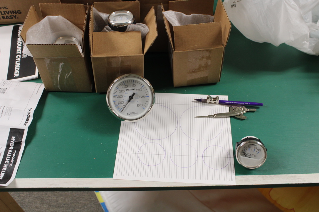
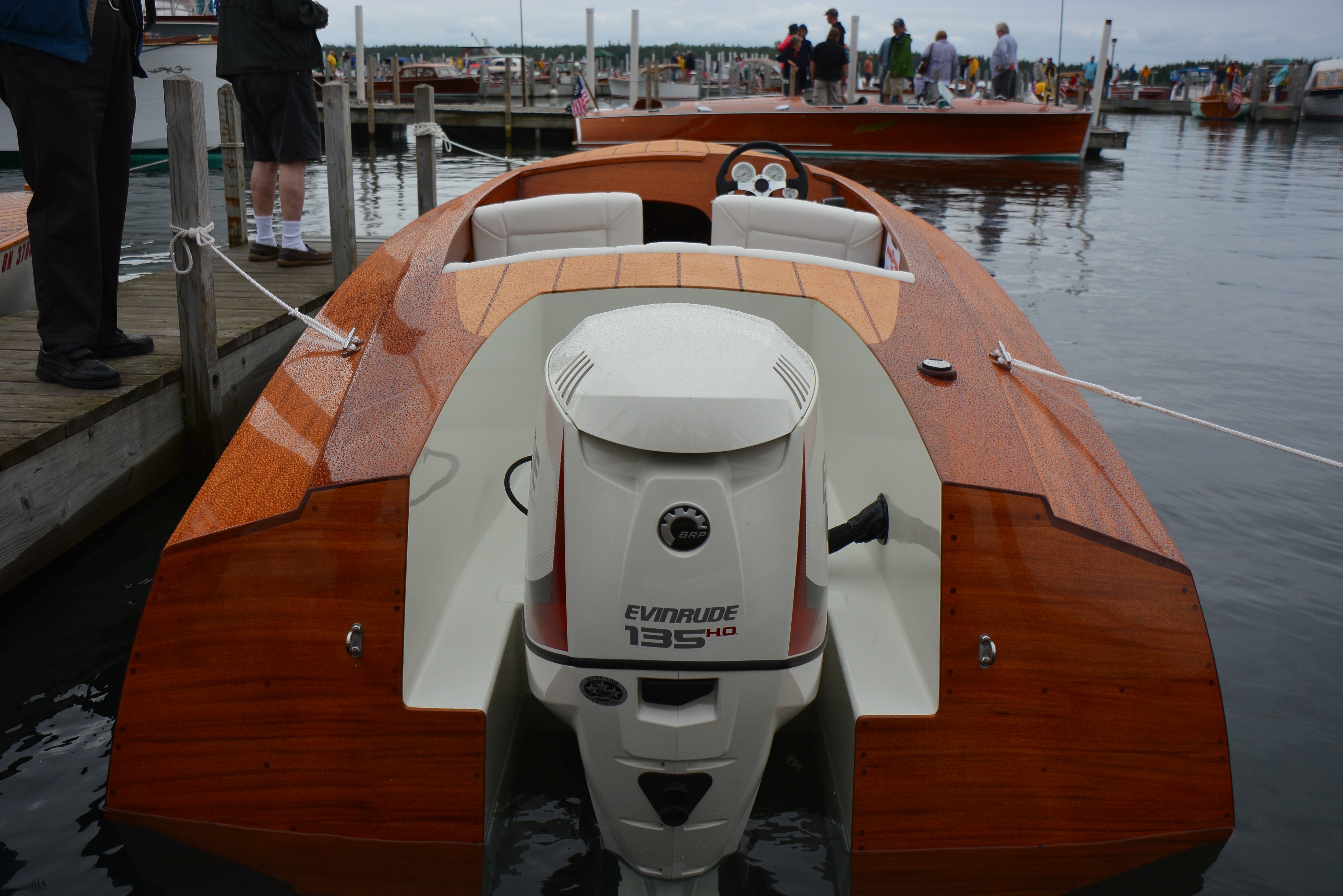
Another big step was to define the dash layout for the steering wheel and gauges. I will be using a Suzuki motor, and along with recommended gauges.
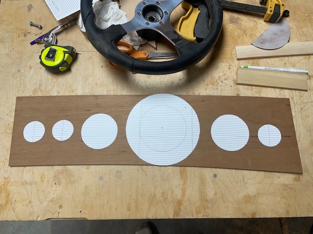
From the specified diameters, I cut patterns to visualize how the dash could look. It was asymmetrical due to five gauges and the wheel helm, and I preferred the choice below.
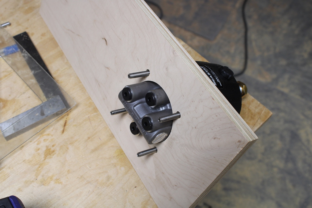
I did some test cutting, to make sure the parts would fit. I had a hole saw for the 2″ gauges, and had to customize routing for the larger holes. I used a bearing guided rabbet bit, changing the bearing size to enlarge the hole as I needed. Then, I followed with a straight bearing bit from the opposite side to finish the hole. Supplemental holes were drilled from the helm layout pattern.
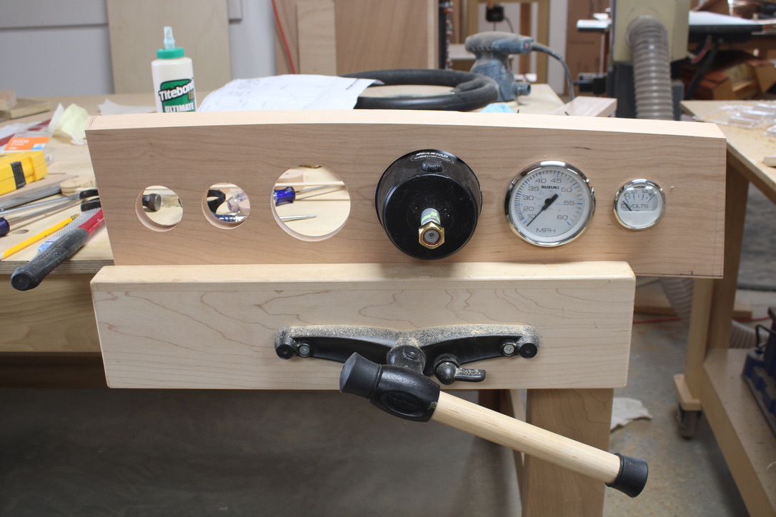
Then I made a final layout, and drilled and routed holes, sanding as needed to fit. I picked old school gauges to fit the attitude of the boat, even though it has an open bow, a ski pole, and a ladder for modern convenience.
The dash was installed at a tipped angle to allow comfortable view from the driver’s seat and knee clearance for the wheel. Space was needed behind for the steering hydraulic lines, and electric wiring for the gauges.
This is the kind of progress that gets a satisfied sigh with a check off, and back to the notes list for the next up assignment.
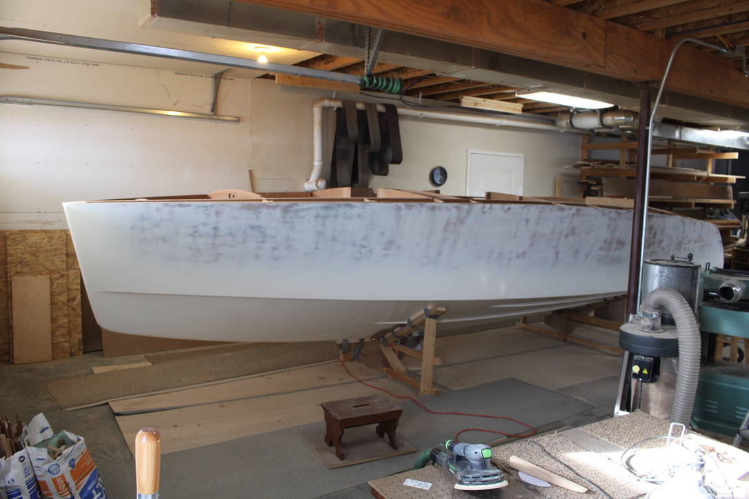
The photo below shows the hull after the sides and bottom were covered with fiberglass fabric embedded in epoxy. Fairing was completed before the e-glass, and the evidence can be seen in the smooth surfaces and clean flowing regular lines. The dark brown lines on the sides, were where I had to sand through the outer layer of marine plywood. The hull was built using 4″ tongue and groove plywood planks.
Wherever green shows were slight depressions, that were too deep to be faired with the surrounding sanded wood. Those areas were filled by a green two part epoxy filler, and then sanded fair.
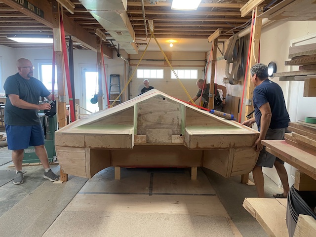
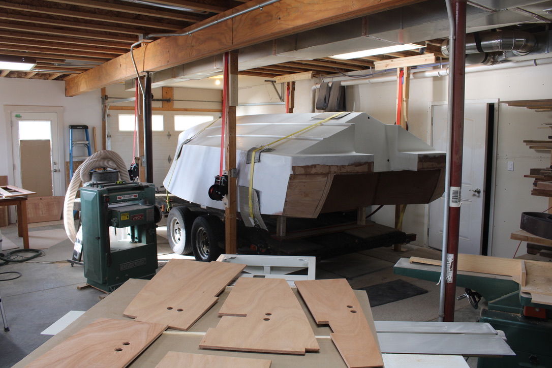
We used the lift system made of four boat winches to raise it up off the floor and rolled a flat bed trailer underneath. Then it made a slow cautious road trip to the paint shop.
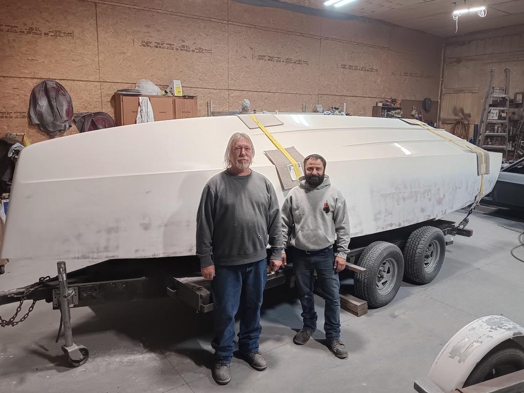
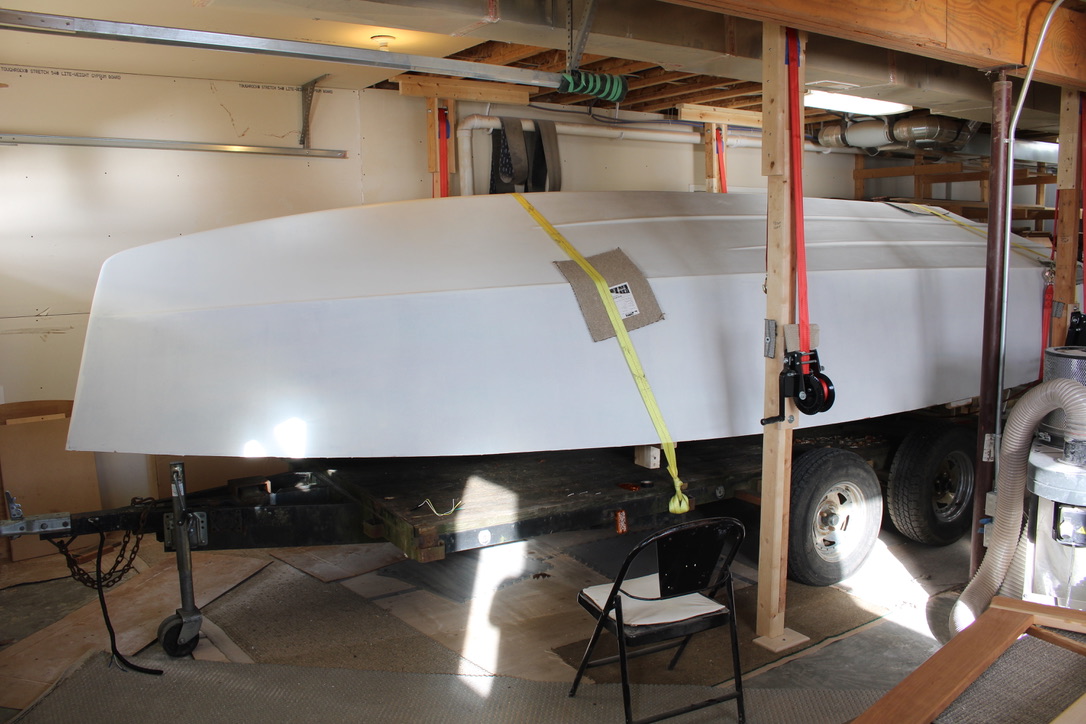
Below is the boat after having the bottom primed and painted with Total Boat Wet Edge, a one part high-gloss, polyurethane topside finish. Over epoxy, it is a very effective water barrier for a couple of days, but not intended for full time immersion. This boat will sit on a lift most of the time, coming out on the water for day play and a few road trips.
Jeff and Kruse both have a couple of decades of paint experience, and did a fine job of finishing the bottom and part of the sides, stage 1.
Back at the shop, with inches to spare on the sides coming in, we prepare to turn it over to right side up one last time.
Here it is back on the temporary cradles, for the final construction work on the top and interior.
With the boat upside down, it was time to put the outer covering of fiberglass fabric over the marine plywood hull planks. Glass fibers are very strong in tension and resistant to abrasion. When embedded in epoxy on the inside and outside surfaces, it creates a strong, stiff and relatively light weight composite structure.
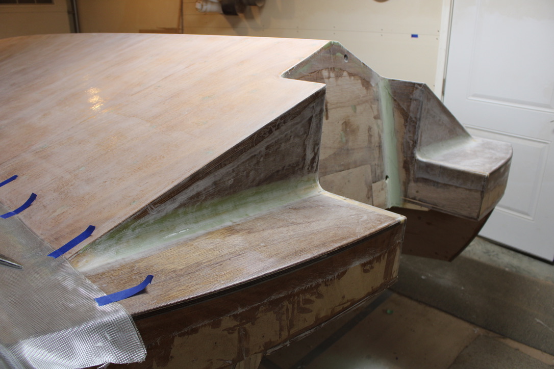
The photo below shows the hull bottom after placement of the glass fabric. The corners have been filled with a thickened two part epoxy filler that were sanded to shape. The back edge of the bottom surface was left as square as practical, for the most efficient water cutoff at planing speeds.
Experts disagree on two main methods of adding the glass fabric: laying out the fabric and then applying the epoxy or brushing a coat of epoxy on the wood first. Since the fabric catches on sharp or sticky things and deforms easily, I prefer to carefully lay it out over dry, sanded surfaces, primarily in one plane, as shown below.
A 36″ wide layer was rolled out and taped, overlapping the previous finished areas. With a smooth under surface, small changes can be made to smooth out wrinkles for the best possible fit.
The downside to this method is that the epoxy must penetrate the fabric, and fully bond to the wood underneath, or risk delamination later. The surface needs to be fully wetted and transparent, but not so much extra that would make epoxy flow zones. The application begins, rolling epoxy from top down, working out wrinkles as we go.
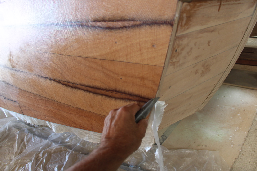
When the epoxy has set up to the stiff, not sticky stage, before it gets hard, the edges can be trimmed with a sharp knife.
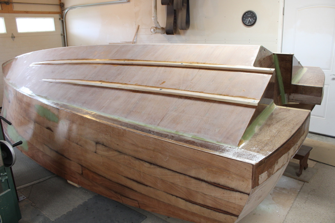
Next strakes were added, and rough sanding all over with 80 grit to allow best primer and paint adhesion. The hull planks of 4″ tongue and groove marine plywood show through on the sides. The dark lines show where the top ply layer was sanded through, and the green where low spots had been filled for final fairing.
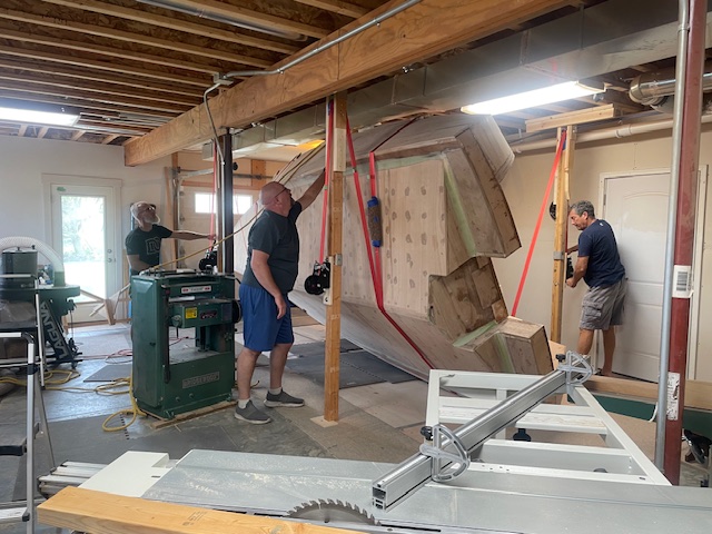
My shop is not equipped to spray paint , so the boat was loaded on a flat bed trailer and slowly hauled five miles to get professionally painted. This is on the return trip, preparing to lift the boat with the four heavy duty winches mounted on the temporary posts.
There are many ways to slow down a big project like building a boat, which happened but it is off and rolling again, passing this significant milestone. Work on the bottom is completed and following a final flip, this boat is intended never to be upside down again.
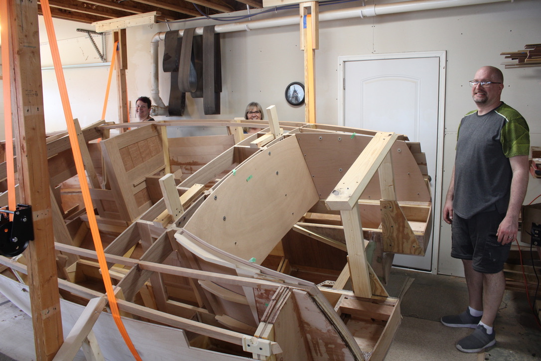
The construction of this 20′ speed boat started around January 2023 and by July the cross frames were connected with the keel, long stringers, and the hull planks on the bottom. It probably weighed 400 pounds and was a fairly easy job for a dozen relatives and friends to turn. We used two heavy nylon rope loops held by 2 x 4s, screwed to the ceiling joists to support the weight. It just took a little muscle to settle it on to the custom cradles made specially to fit the bottom.
Then, I went ahead with some interior work: mounting spaces for gas tank and battery, floor parts, seat framework, and top trim lines. It was ready to turn again.
Second Turn – February 2024 to Upside Down
For this turn, we added a couple of 8:1 Block and Tackle pulleys and some extra rope loops to help rotate the added weight, which I estimate was then around 600 pounds. Andrew Alger and Jeff Margush are studying the situation.
The pulleys barely did the job, and required a fair bit of supplemental muscle from all, Steve Rimes and Todd Lederman, among others, below.
Here is the satisfied crew that got it done.
With the boat upside down, I added a second plywood layer to the bottom, and fit the side hull planks. Knowing the trouble we had with the last turn, and that it was heavier now, Andrew Alger engineered a new system of four posts and winches to carry to load.
Third Turn – April 2024 Back to Right Side Up
For the new process, I made four posts which rested on the floor, and were temporarily screwed to a mount plate at the ceiling joists. They had blue plastic covers from table placemats, to reduce sliding friction of the strap across the top. The winches were bolted on at a comfortable working height.
The boat was on fairly high cradles, and the system worked quite well, turning the 20′ wooden speed boat back to right side up with only a few people helping.
After that, I built out the stern extensions at the back, finished the side planks and added more interior framework. This added more weight than we anticipated. Jeff Margush adds his thoughts . . .
Fourth Turn Attempt -Failed Try to Upside Down – August 2024
Then it was time to flip it upside down again. This time just three of us, Andrew, Jeff and I tried to make the turn. My first impression was that the winch handles seemed more difficult to rotate than how I remembered from before.
On the first try with the post assembly, I just put plastic strips across the post tops to help reduce friction for the nylon strap to slide. It had worked well as we were rotating a side down, with the center of gravity going down also.
But, this time, pulling the boat upward, the orange strap got really tight, pulled the blue plastic strip off and wedged itself between the post and the side guide.
The boat was now a couple hundred more pounds heavier, and the extra force required to the winch handles, pulled them out of alignment. That folded the strap, increasing friction there as well.
In addition, when we tried to get the boat lifted on one side, the low center of gravity caused the boat to resist rotation and made the boat slip on the straps.
We did get the left side rotated up about 1/3 of the way, and then turning the cranks got so hard we had to stop the attempt. We reversed and gently let the boat down to the floor.
Note: the back right post is already removed after the failed attempt and the boat is peacefully resting on the floor.
Fifth Turn Attempt – 2nd Failed Try to Upside Down– September 2024
To improve the system, Andrew made some heavy duty rollers, with large washers welded to the metal cylinders, spinning on 1/2″ bolts. The flanges helped to prevent the strap from getting caught on the side of the post, and the metal cylinder turned so freely as to almost eliminate the friction.
However, the weight of the boat at this point still overwhelmed the capacity of the winches and straps. Also, the boat kept slipping when we tried to raise one side, and it look like a risk of falling over too fast if we did get it rotated past the vertical position.
There was a little head scratching before we quit this attempt and lowered it to the floor.
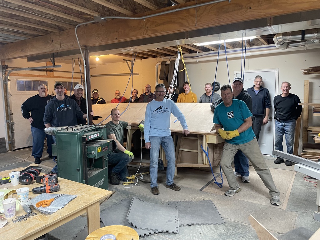
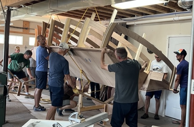
Sixth Turn Attempt – Successful 3rd Try to Upside Down September 2024
Once again, Andrew helped to improve the turn system, and suggested new heavier duty winches. They also had an improved gear ratio of 8:1 which made turning them easier. This time, instead of just having the strap across the bottom, I also fully wrapped the strap all the way around the boat, which helped reduce slipping.
Below shows the tweaking needed to avoid hitting a light or dragging hard on the floor, but this time we succeeded in getting the boat turned over.
On the short legs again, it is now ready for final fiberglass and epoxy coating on the bottom, and then primer and paint. This is hopefully the last time it will ever be upside down.
Below is the response from friend David Beale when hearing about the delays:
“I’m guessing difficulties in flipping the boat during the build process probably never made it into your time calculations when starting off on the build – which would make it similar to so many of my own projects. Moving something of that size is clearly not easy!”
True enough. David speaks from experience as he is an adventurer extraordinaire. Besides mountain and wilderness exploration, he built and worked a beautiful 19th century farm without fossil fuels for a decade and a half. You can read about some of his amazing adventures on https://haymanfarm.blogspot.com/
Next up is finishing the bottom of the hull with epoxy over fiberglass fabric to prepare for painting. . .
Fairing a surface is the process of making the curves regular, that is, without noticeable hills or valleys. Problems are not easy to spot visually at this stage, but will become very visible later when a glossy paint or varnish is applied.
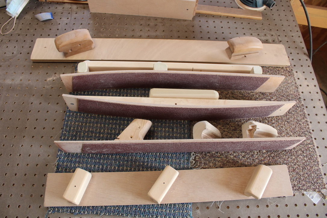
It would have been easier, if I had designed it with contemporary flat plane surfaces, but no, it had to have inner and outer curves. The secret according to Jeff Margush, is to make special sanding boards that roughly fit the curves of the boat hull. Below are the five most useful of the ones I made, starting from the top:
Half inch plywood with 80 grit belt sander paper, held by contact cement.
An adjustable convex sander, 40 grit, 1/4 inch plywood for easier bending.
A concave surface sander, 40 grit and 1/4 inch plywood.
Three handled bendable straight sander, 40 grit, 1/4 inch plywood.
Three handled bendable sander, 80 grit on 1/4 inch plywood.
Below is the convex sander, which has the removable wedge at the top, to allow more precise adjustment to the slight barrel back contour.
This sander below is used to smooth the hollows, the concavities, including areas that were far enough inset that I needed to add some epoxy filler. Fortunately, when cured, it is formulated to sand nearly the same as the plywood.
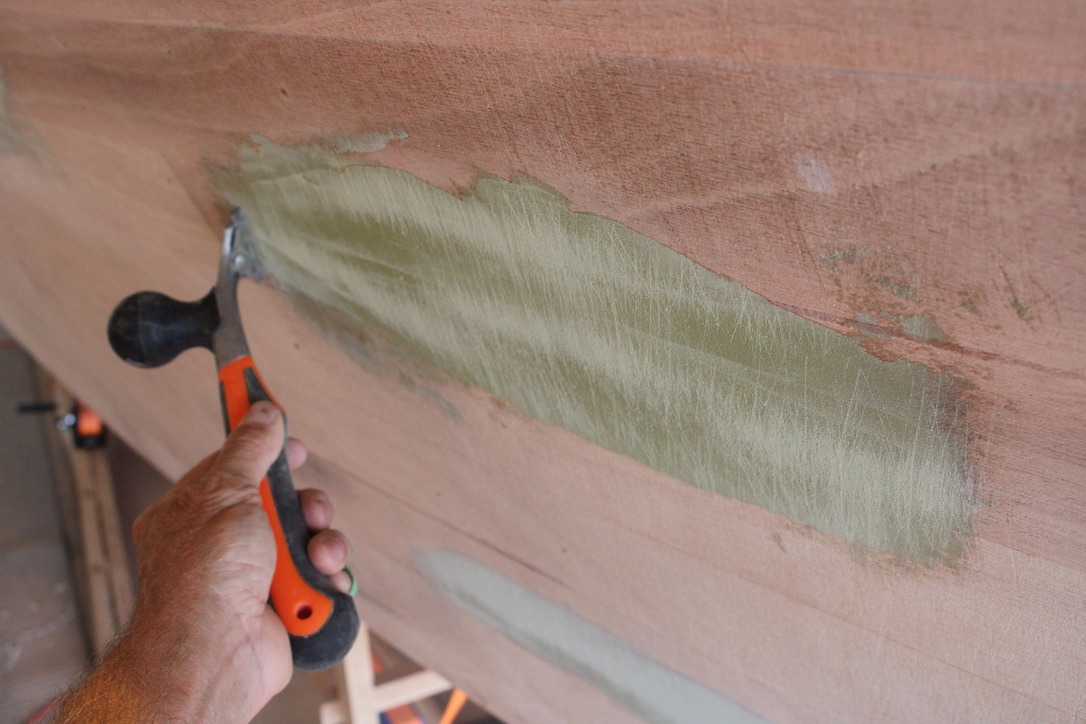
Sometimes, for special concentrated shaping the scraper is the perfect tool. It has a removable carbide insert blade that is really useful.
At this point, the boat doesn’t look so great with sanding through the first layer of plywood, and the added green filler. But if you close your eyes, and move your open palmed hand over the hull surface, you can feel if the hills and valleys are still there, or just one regular curve is left.
It is a great sense of accomplishment when you can no longer feel where the side planks join, or where the green surface starts.
After many trips around the boat, hand checking and sanding, I believe the fairing is 95% plus done. But I reserve the right to do an inspection after the glass fabric and epoxy are added to the bottom.
No matter what, it is a great step of progress to be past this stage.
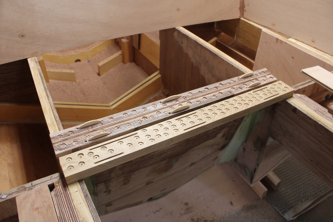
The hull sides are now complete, with the outer planks of 1/2″ tongue and groove marine plywood running horizontally, and the the inner strips 1/4″ marine plywood , crossing vertically. It is now time to finish the seat framework. The two jump seats have base structures joined to the divider wall, and anchored to the bottom planks.
The next step is figuring out where the seat back should go, and these pillows serve as a 3D examples to see how it might work. As I looked at them, it crossed my mind that I could save some money and bother, and use pillows just like that throughout the boat. After all, the boat is not an historic replica. Then I imagined what might happen after they got good and soaked a few times. . .
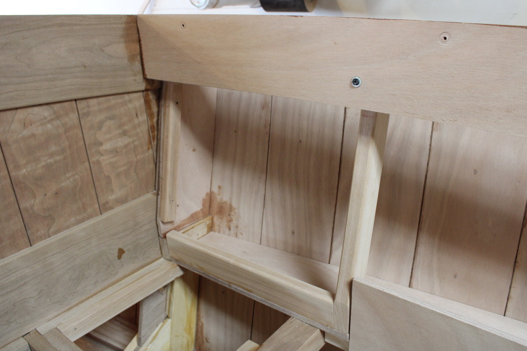
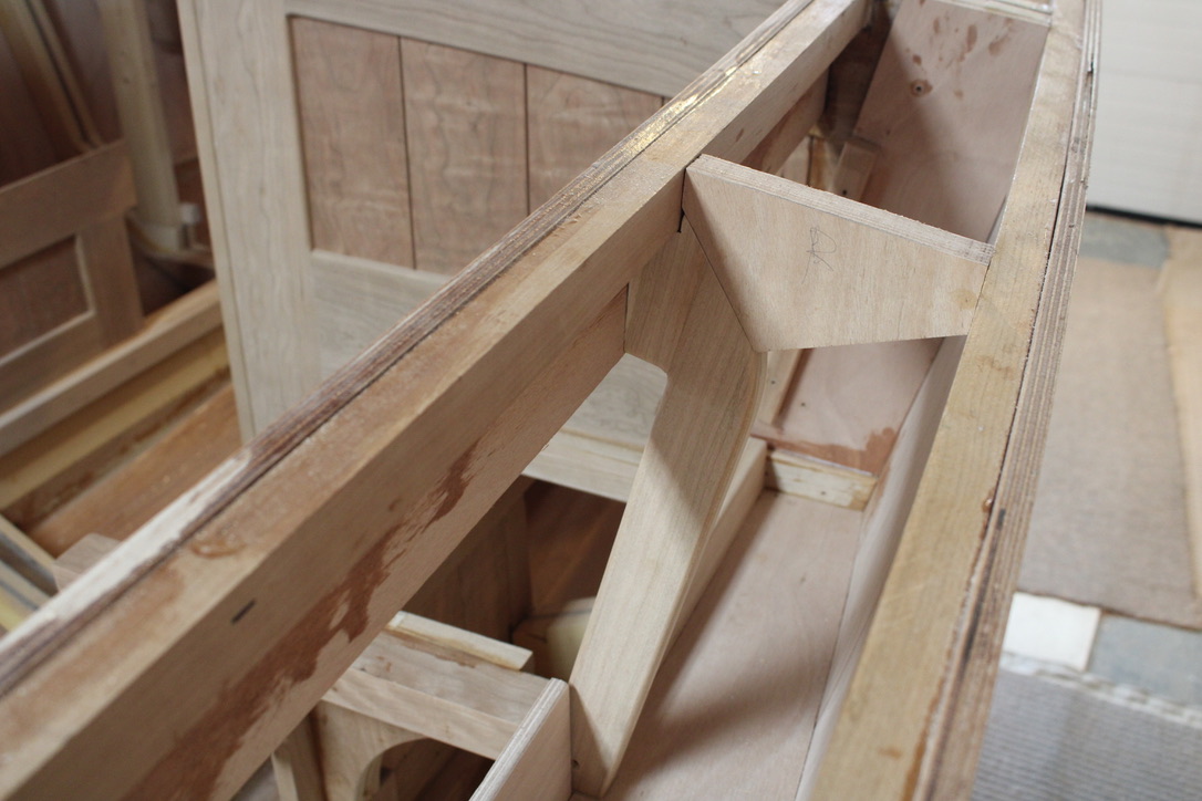
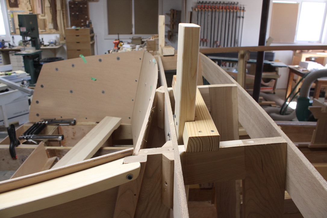
I started by gluing a runner against the divider wall at a back angle set by imitating a comfortable chair. There was not great place to attach the freestanding post.
I added a spacer in front of the post to hold it at the same angle as the side runner. Then, the triangle block connects the inner face to the outer hull wall, and stabilizes to the whole frame assembly.
A second overlay plywood gusset ties it all together and the engineering questions are laid to rest. When that assembly is epoxied together, it will be strong enough for the wave bumps that will come.
No commonly available data can tell exactly how many pounds of drag a ski pole must pull. So, it becomes another one one of those challenges in building a boat that requires some thoughtful estimation. For a skier, the drag weight has to be in the range they can actually hang on to, which I will guess to top out at something a bit above their body weight.
Pulling tubes, however, is a different story, which is why most of the ski post retailers say not to pull a tube. My grandkids have never understood that logic, and have been known to jump five riders on two tubes. If they lean back, it can almost prevent the boat from coming up on plane.
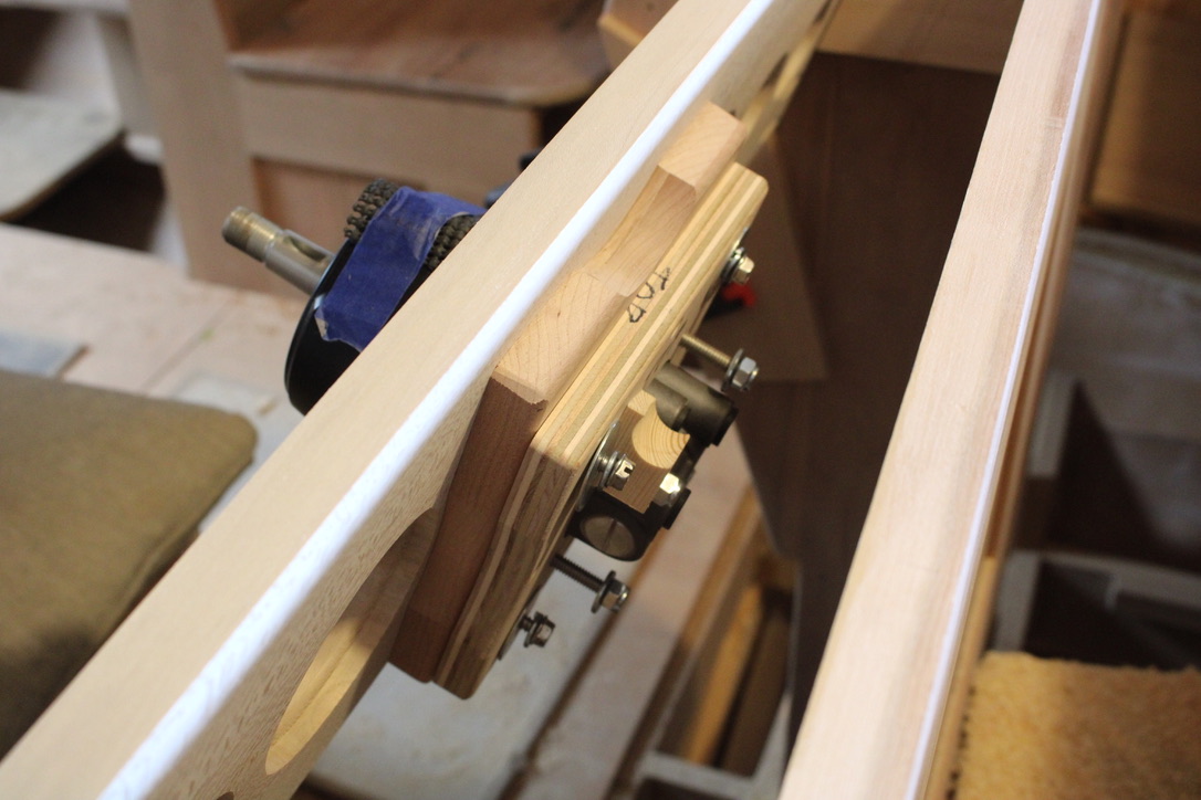
A typical ski rope is made with a 1600 pound max of tensile strength, and in combination with a 2-3/4″ Mastercraft aluminum pole, is not likely be the weakest link. So, the mounting frame work, which will be centered between the seat back and the front of the engine well must be “super” strong.
Creating Front to back stiffness
I started by adding inner and outer support plates to the triangle frames which had been dowelled to the bottom boat longitudinal beams.
Making the top plate
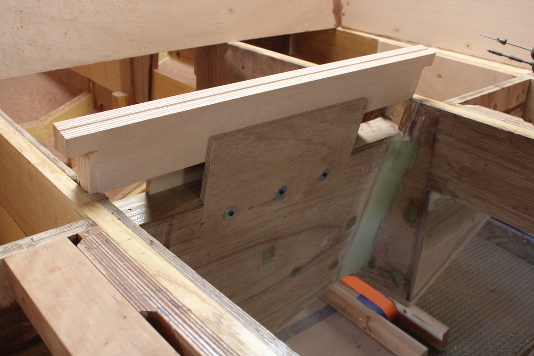
The third piece of the vertical leg was added on the inside of the front sandwich. Then three pieces of Baltic Birch plywood were laminated and epoxied into place at the top of the legs.
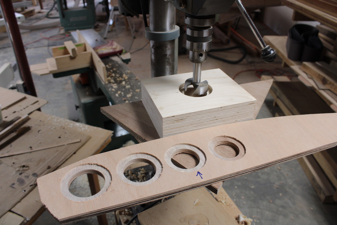
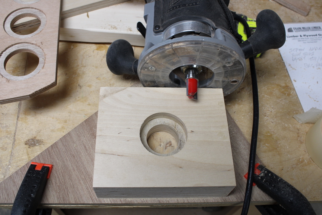
The ski post is 2-3/4″ wide, and don’t have a drill bit that exact size, so I had to cut it in stages. First, I used a Forstner bit and followed with a bearing guided router bit to enlarge it. Eventually, experimenting created the right sized hole.
After cutting the ledge a bit deeper, I used a flush-cut bearing bit to finish the hole through.
Last, I added a base support to hold the bottom of the pole. When the back seat top piece is epoxied into those front notches, it will add some side to side stiffness, and I am betting on the framework to pull two tubes strong with out complaint.
This is just a single example of many things in a boat building process that need to be researched, and thought fully worked through. When in doubt, overkill engineering tends to help me relax as I go on to the next chapter. But, I am pretty confident that when the first skier hangs on to the rope, it won’t let us down.
After what seems like endless days building the boat frame, shell and interior parts, it is high time to do the final engineering of the back, and close it in. When I started, the original plan was for an outboard motor with a 20″ vertical shaft, but I became concerned that the transom height was not far above where the water line will likely be.
Even though there is a separate back wall to the motor well, I did not want so much water to come over the transom as the boat slows down. Also, there was a concern that having the motor mounted lower to the water could allow water coming into the exhaust ports. So I needed to rebuild it 5 inches taller for the next larger motor size.
The 2.5″ thick transom was made by epoxy laminating five sheets of 1/2″ marine plywood, and then mounting it in grooves of the long beams. This is not a casual, glue a piece on the top, as this area needs to be strong enough to successfully hold a 500 pound motor and the push/pull that it provides. Not to mention that the most stressful time may be crossing a bumpy rail road tracks.
Routing for a Crossover Sandwich
So, i first clamped in some plywood scraps to make a temporary guide fence for the router, inside and outside.
This is the top view showing the areas cut out and the angle brace that connects the transom to the keel. Plenty of dust came from routing the sides.
Here are the sandwich sides prepared to hold the new transom extension, which was made to fit down into new grooves on the sides. Overlapping wood parts gives the most epoxy gluing surface area and mechanical strength.
Corner filler pieces were added and then the assembly was biscuit joined to a strong piece of white oak to cap it off. Finally, I drilled a bunch of shallow holes with my Forstner bit so when the thickened epoxy attaches the parts, it adds strength in an imitation of many dowel holes.
This is probably the expression of a tendancy of mine that lead coworkers at Swartzendruber Hardwood Creations to think that sometimes my work was a bit “overkill.” Maybe, or maybe not, but in on the back of the boat, I can live with the chances.
The transom was done, and next up was building the internal support for the ladder going next to the repaired transom. With the improved height of the transom, and ease of getting on and off the boat, it should be better performing and more useful also.
Building a boat is a lot like climbing the Lake Michigan dunes, a short step up and a slide half way back. But where would you rather be than watching the grandchildren explore, jump off the cliff, run full speed down, occasionally tumble, with maybe a bit of sand in the mouth. Nothing that a hotdog won’t wash down.
All boats have some curved surfaces, and the most beautiful have many curves, all hopefully contributing to a cohesive complete package. Some modern boats have curves in only one plane, and that makes construction easier. But traditional wood boats, and ones I wanted to pay respect to, have surfaces with curves both ways. That makes hills or valleys and it gets complicated.
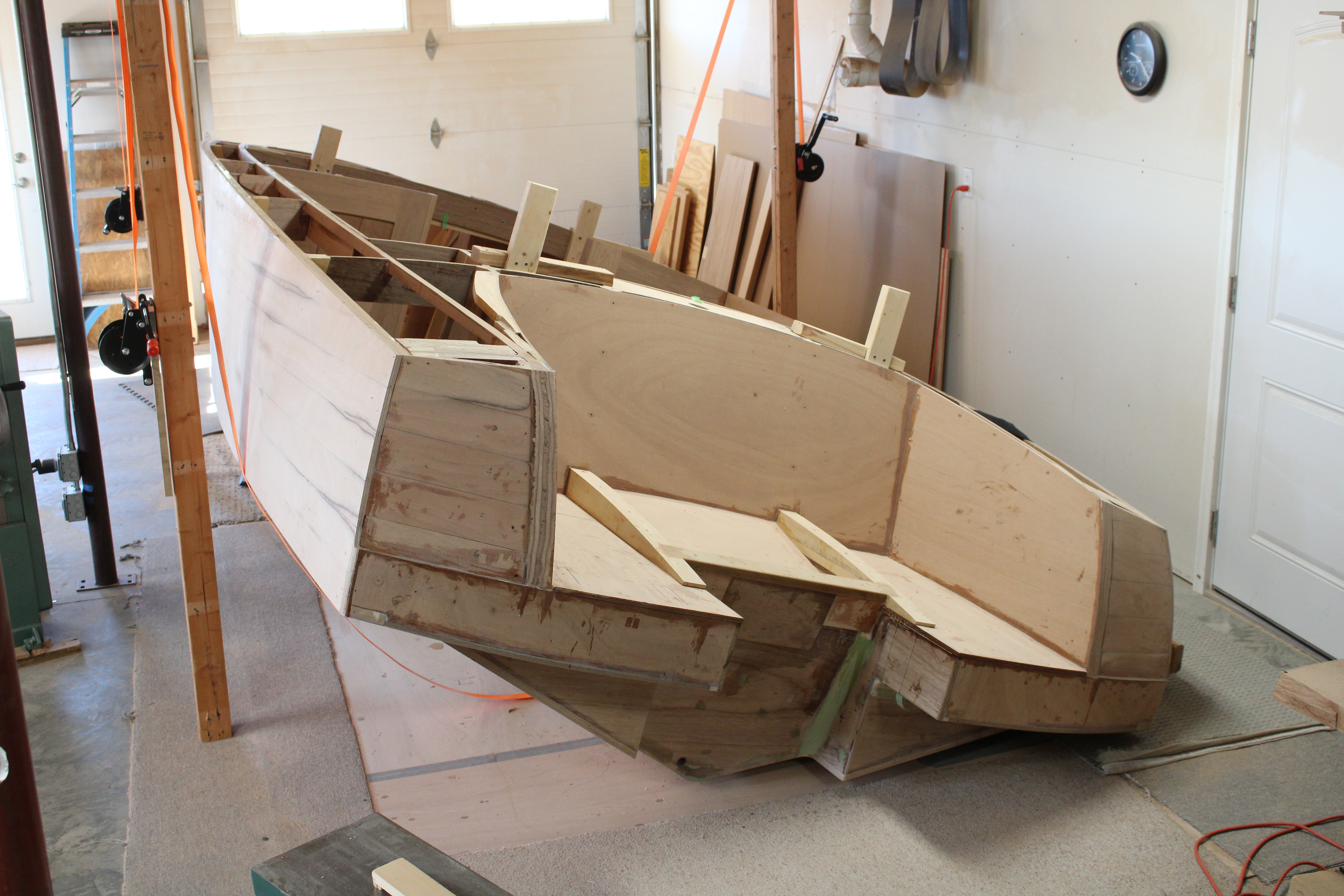
Below is the boat at completion of setting the long trim moldings that define the cockpit, and end at the stern. Now is the time to figure out the shape of the stern.
At the back on the outside, there is the inward curve or tumblehome, that adds width and buoyancy to the back, and just looks cool. And since an outboard motor on a wood boat can look out of place, the sides were extended to enclose it a bit.
New shapes usually begin in cardboard, then on to plywood if I need a rigid pattern. The piece of cardboard laying on top is to visualize how the wall of the engine well might look, and of course, it just came out curved as well.
That makes sense considering the back wall is also curved.
Then, to finish the double curve on the stern sides, internal runners were made for the first layer of tongue and groove shell to follow the side curve.
Eventually, it will be contoured, with both directions relating to both curves at the corner. The complication may be forgotten, and a complimentary form left standing. Beauty has a price.
In the nearly five years of having a couple of boats in progress, the times to turn it over have occasionally gone smoothly, with a few scary moments. This was the first turn of the smaller boat when the framework was lightest. I just got some heavy duty nylon rope and attached some T-bar 2 x 4s to the rafters to hang it.
Light weight first boat turn
The next time had more oops and inefficiency spreading of the lifting power. The ropes did not behave as well as expected and a little floor bump occurred . . .
Heavier and more muscle needed.
But apparently all’s well that ends well.
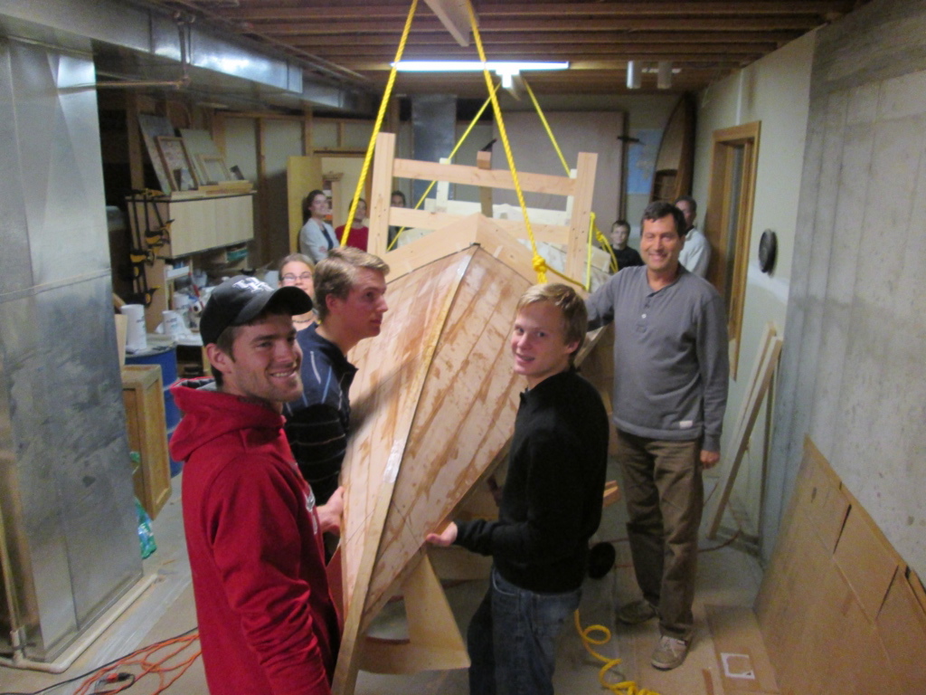
Getting the boat out of the basement was a pretty tight challenge, but finally made it.
A couple of inches top and bottom.
And eventually it floated.
Les Chenoix Boat Show
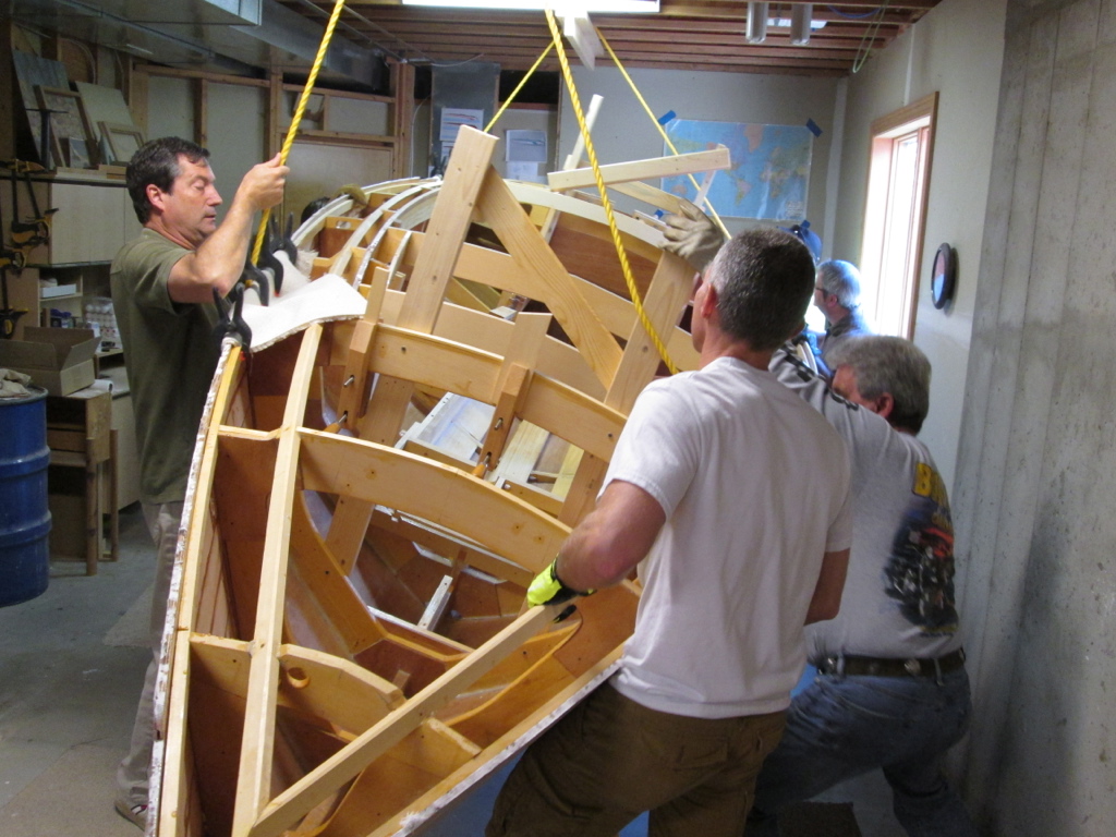
The second boat, currently under construction is larger and made the first turn with a bit more muscle and finesse. We just about took out the light at one point.
Second boat, more weight and muscle, narrow miss.
The next turn got more complicated with a tangle of ropes that were difficult to adjust, and left a few guys holding the proverbial bag. This time we had trouble clearing the heat duct because the front pulley system failed and left it hanging down.
Front Pulley broken. . .
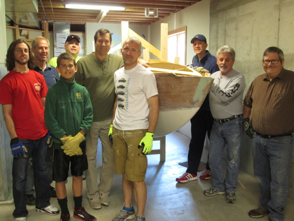
So, in the garden, look for help from someone with green thumbs. In the shop, look the guy in the green gloves, like Andrew Alger NEI above. NEI may not be a Purdue degree, but It stands for Natural Engineering Intelligence, and he has solved more than a few of our “make-something-work” crises.
Andrew came up with a new plan, as the boat needs a few more turns, and is getting heavier all the time. He suggested getting four reversible winches, to hang on support poles, with heavy duty nylon strap. I dutifully followed his plan and voila’ it became quite easy.
Two of us turned the winches to pull up on one side, and the other two released the strap to lower. A few adjustments of height and soon it was sitting right side up on the cradles.
All smiles for the success!
But for the two minute trip of the whole drama, check out the link below.