
The transom leads the pack of all of the engineering challenges presented in boat building. In my case, it will need to be strong enough to hold the weight of a 500 plus pound outboard motor, with all of the rotational forces of acceleration and turning. Last, but not least, the transom will need to stay intact in the bounce of choppy water, and the serious bumps from road pot holes and railroad crossings.
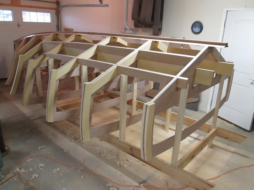
The keel stem and long boards are looking strong enough to bear up to normal water pressure forces and the forward pressure from the motor. Next, in order to model where the transom would go, I cut a pattern out of cardboard to visually evaluate the best place. The tip approximates the mounting angle for an outboard motor.

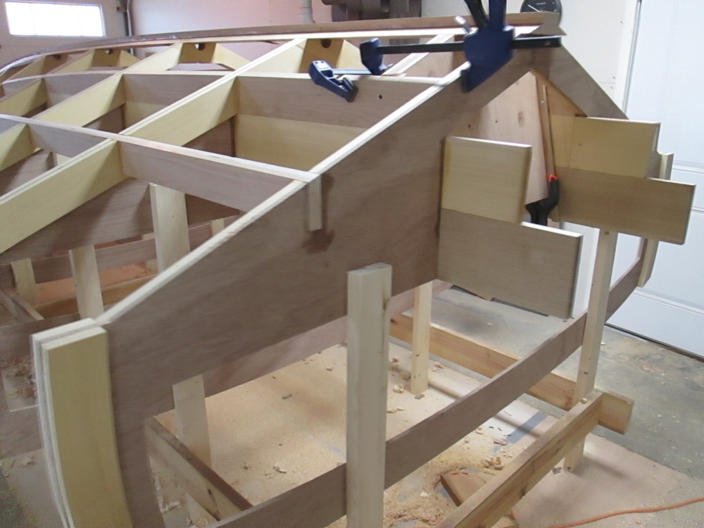
I picked a location inside the first cross frame and screwed a slat at the recommended 13 degree angle to act as a guide for the router. Then, I routed a 3/16″ deep groove, 3/4″ wide for the end blocks on both sides. Much greater strength is gained with a cross grain stop.

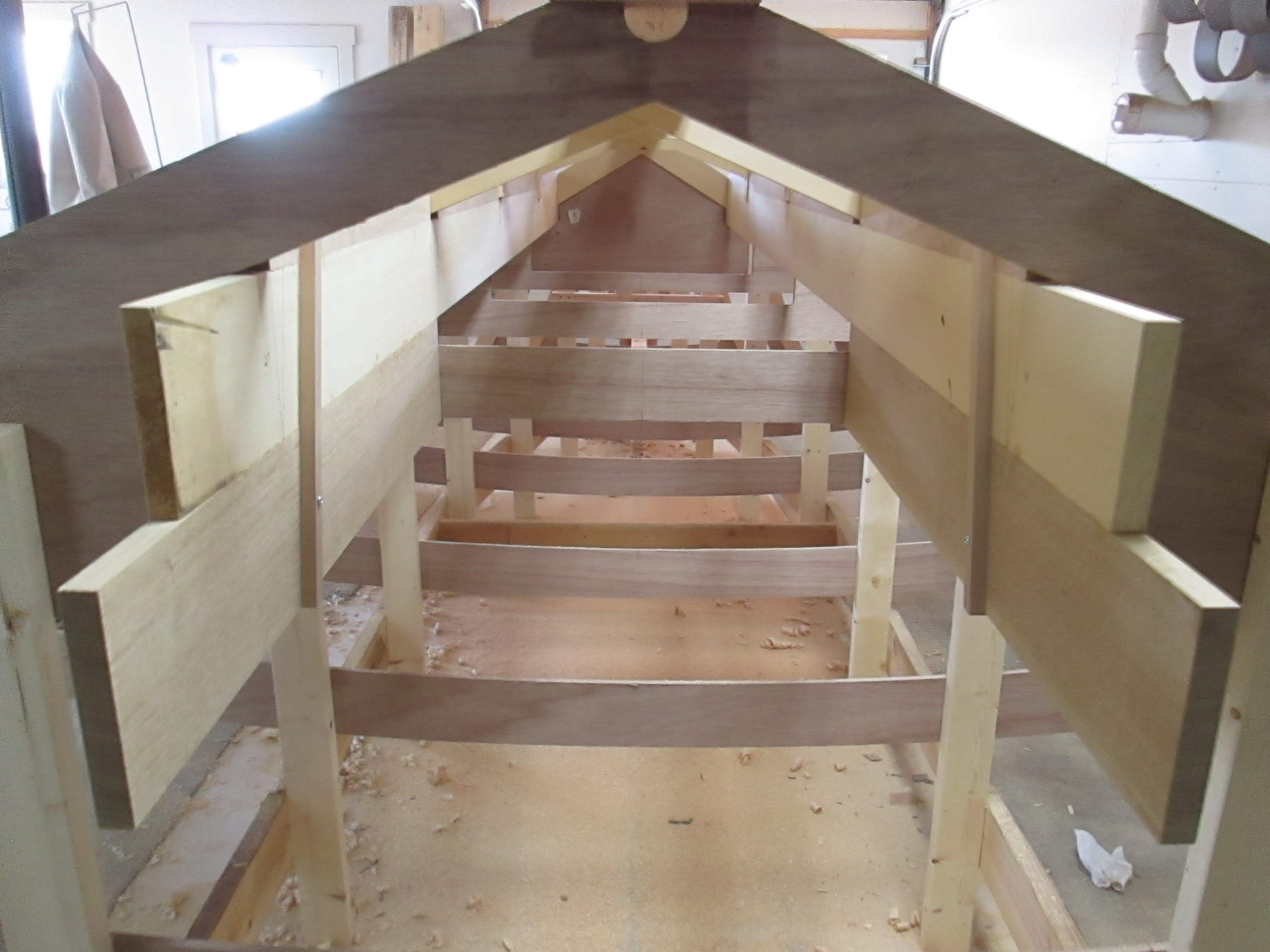
Here are the stop blocks in place, and a temporary view through the sub floor transom and fuel tank space.
The transom was laminated from four pieces of 1/2″ marine plywood with epoxy. One more 1/2″ ply will be added to make a strong motor mount plate.

Once the transom blank was adjusted to fit the keel, and inside the runners, it was epoxied in place, against the cross stops.
Below, the keel has been cut shorter, and the first frame partly cut out to reveal the motor mount area. The scrap pieces are temporarily used on the transom help to spread pressure evenly as the fifth and last lamination is epoxied in place.
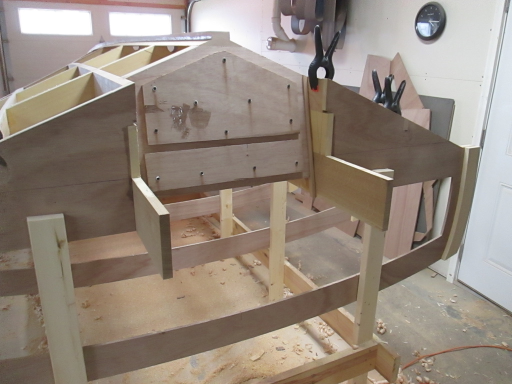
The rest of the stern will be built out when the boat is turned over, adding more transom support structure, but that’s for another day.
