Step / Bench in the Motor Well

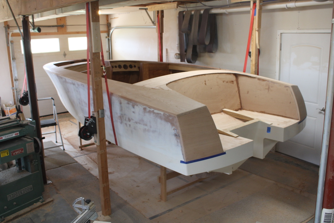
This boat has a generous motor well, to allow for a ladder and a step to climb back aboard. Incidentally, this photo shows the method used for turning the boat over a few times. Those are trailer winches mounted with straps going over a metal spool and under the boat.
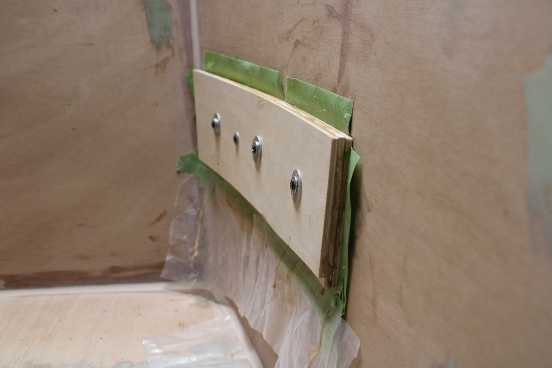
Since the sides and back of the wall are all curved, I needed to assemble some support blocks from plywood pieces thin enough to be bent and glue laminated.

Below is the glued up assembly of three 1/4″ pieces of plywood.
After the glue set up, I shaped the pieces to hold the outside edge of the seat / step, and added a single leg framework to support the weight of someone climbing over.
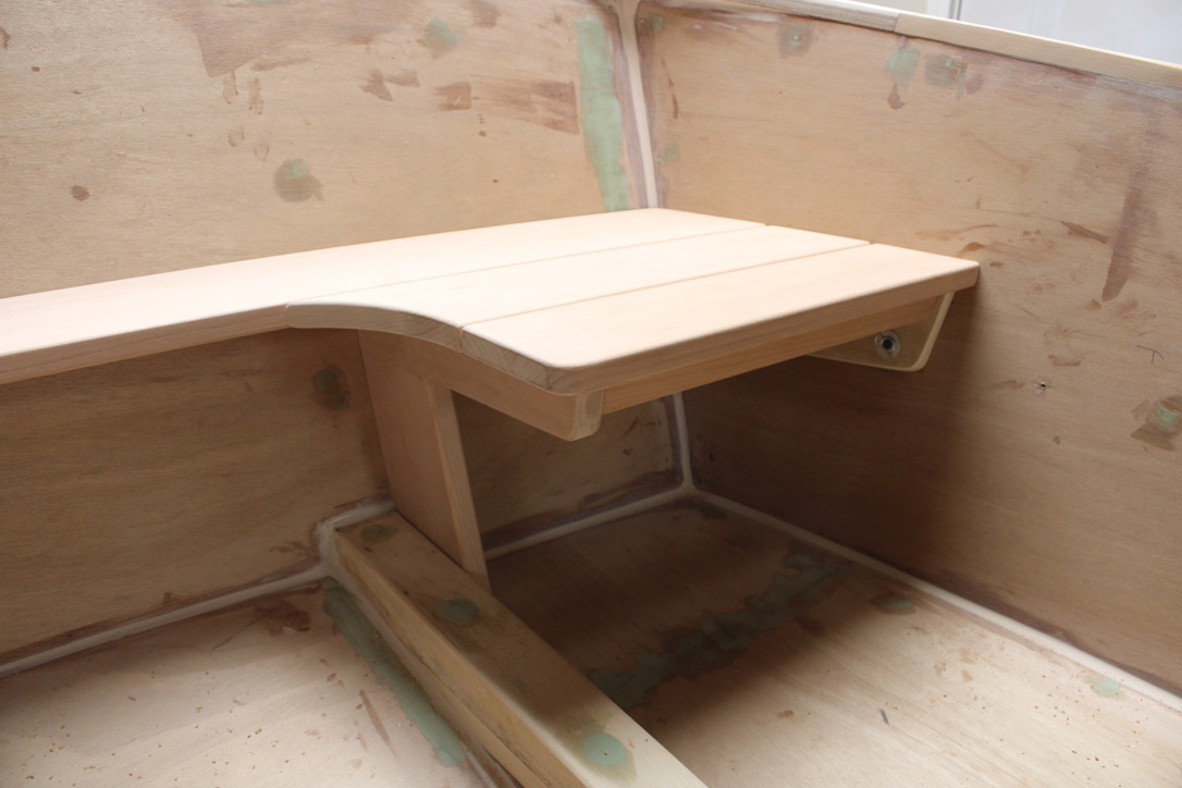
Then, curved slats were installed to complement the curve of the back.
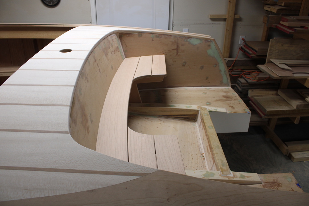
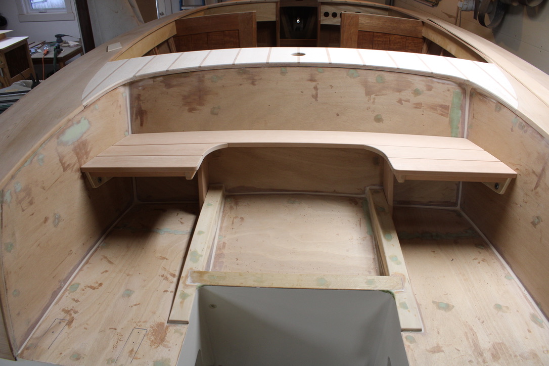
Here, the step is completed and ready for use. With the center cut out, the motor can be tilted forward during launch and travel.
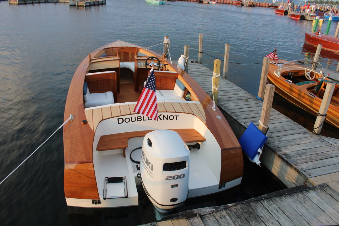
This photo below was taken at Les Cheneaux Wooden Boat Show at Hessel, in the Upper Penninsula of Michigan. With the ladder, step and a ski pole to replace the flag pole, it suggests the possibility of family use for swimming, tubing and skiing.
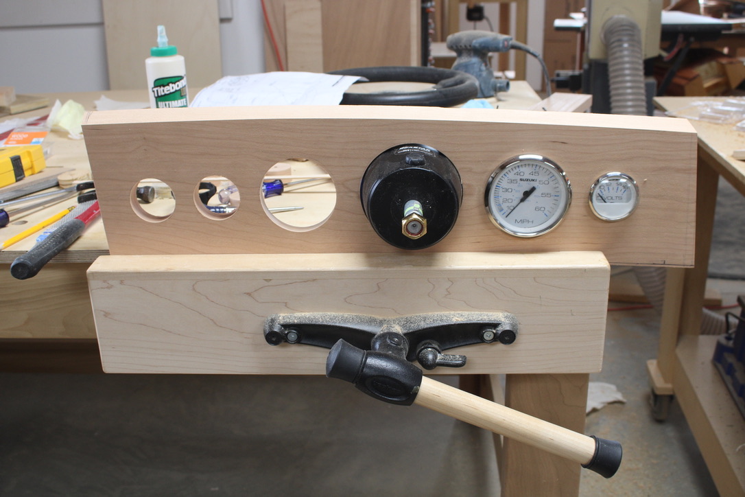
Installing the Boat Ignition and Emergency Switches

If I had planned ahead better, I would have installed the Ignition and Emergency Switches before the dash was permanently mounted in place. But I did not. So I had to devise a method of fitting them without drilling access from the back side.

The first problem was that the rectangular switch plate did not fit on the dash below the other gauges. It was too large and squarish to be pleasing esthetically with all of the other round bases.

The second problem was that gauges and switches usually need a larger hole on the back side of the dash and a smaller opening in the front for the dial and bezel rim to cover. The dash was already fixed, and I couldn’t get access to the back side.

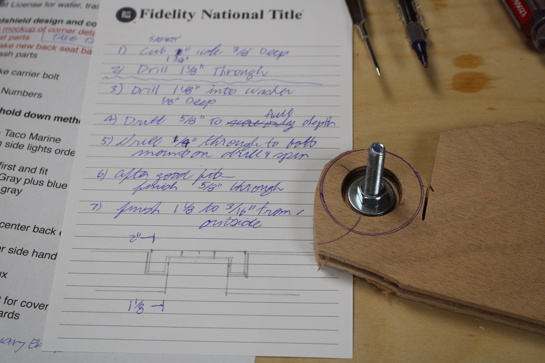
So, I needed to make a wood washer to insert from the outside with the shape drawn on the paper below. The paper lists a sequence that was supposed to get me successfully through the process. That may not have been the final list!

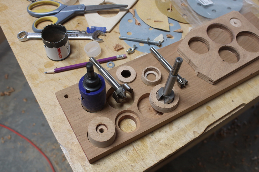
Here is some experimenting, with hole saws, Forstner bits, and a bit of tune up sanding. The two wood washers getting close are between the blue hole saw and the standing Forstner bit. One is laying on the surface and the other is partly pressed into a suitable hole.

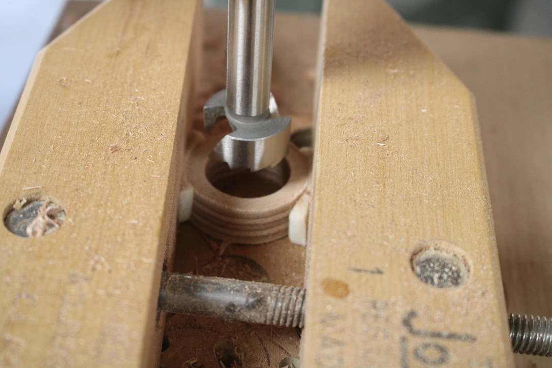
A last step in the process was finishing the middle hole with the Forstner bit, and finding a way to hold it for drilling on the press.

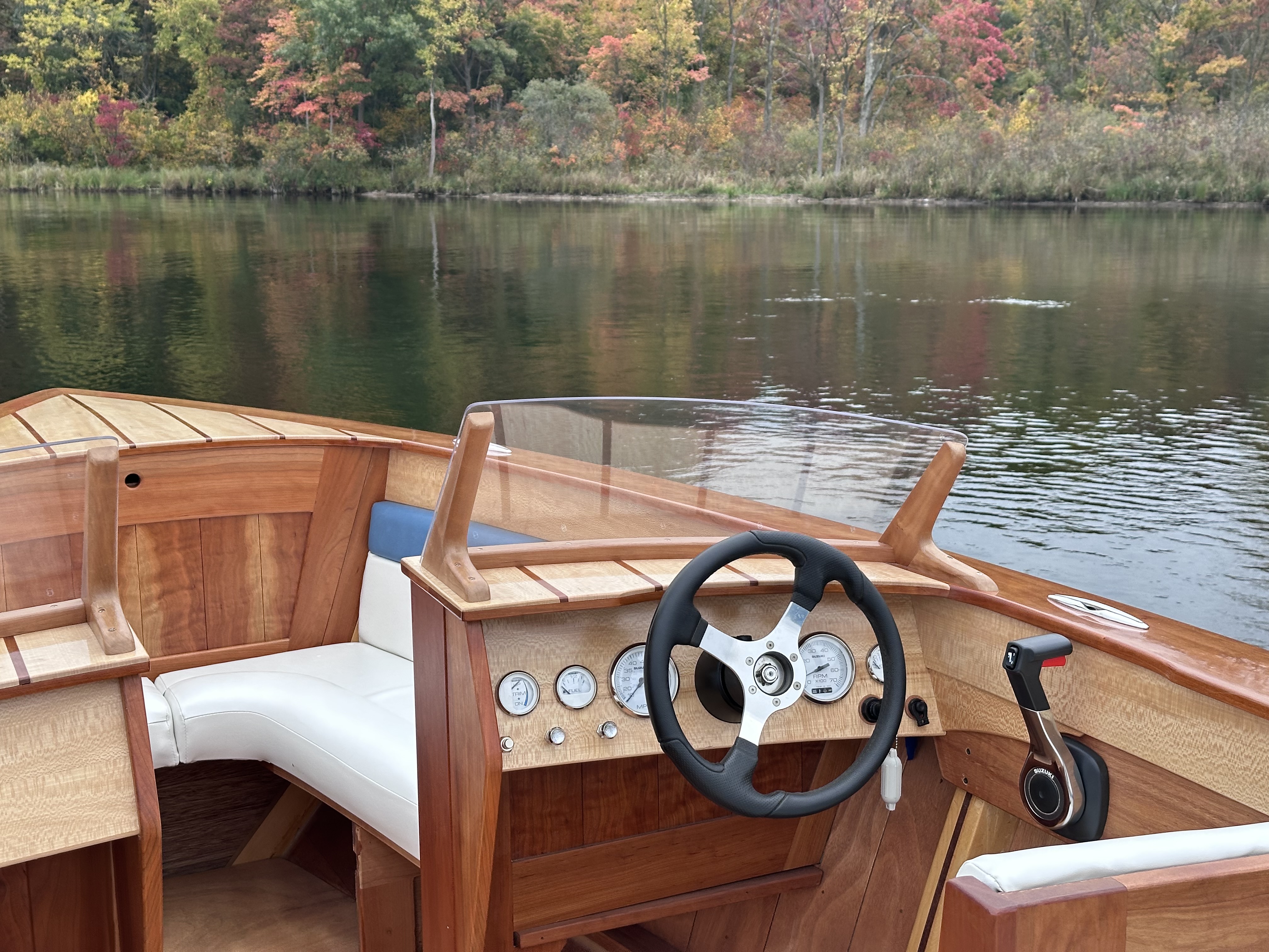
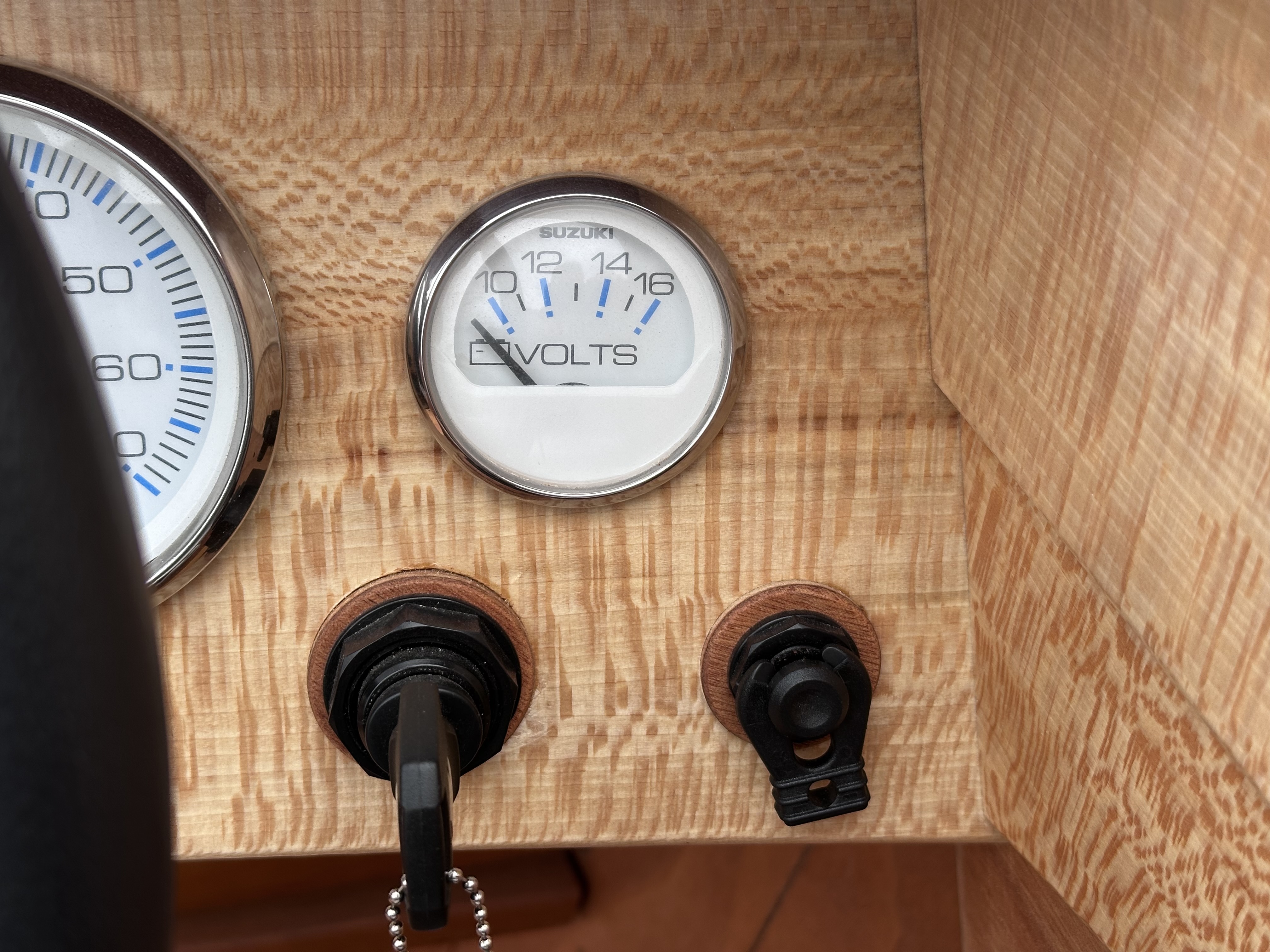
It eventually worked out, after more hours than should have been spent. Below is the dash on a pretty day in the fall in southern Michigan. And that is book matched Cherry in the foward panel.

Here is a detail photo of the end result, with the washers holding the rims of the switches, and glued into the dash. Incidentally, they were made of Okume marine plywood for strength in all directions, and blend just fine with the Sycamore.

A boat is full of surprises, and fortunately by now, I am forgetting many of the detours that took so much time and creative energy to solve. I am finishing three years work on this boat, averaging 10-15 hours a week, which is around two thousand hours. . .

How to Make Face Grain Plugs

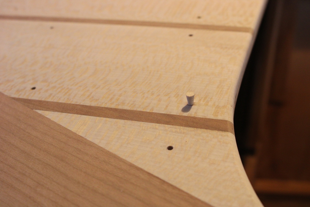
After fairing and sanding the Sycamore Veneer, small holes were left from the screws used to hold the parts in place for epoxy.

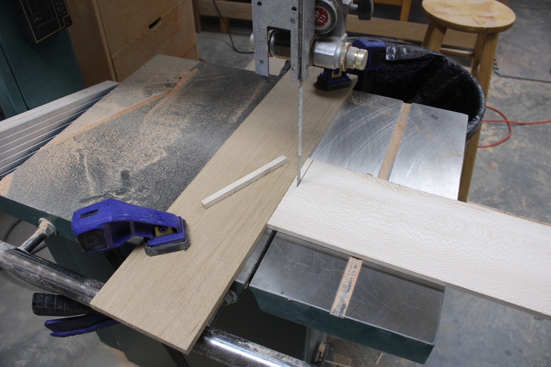
The best matching plugs can be made from face grain. Below, 1/4″ x 1/4″ pieces are cut from the end grain of a 5″ wide Sycamore veneer plank.

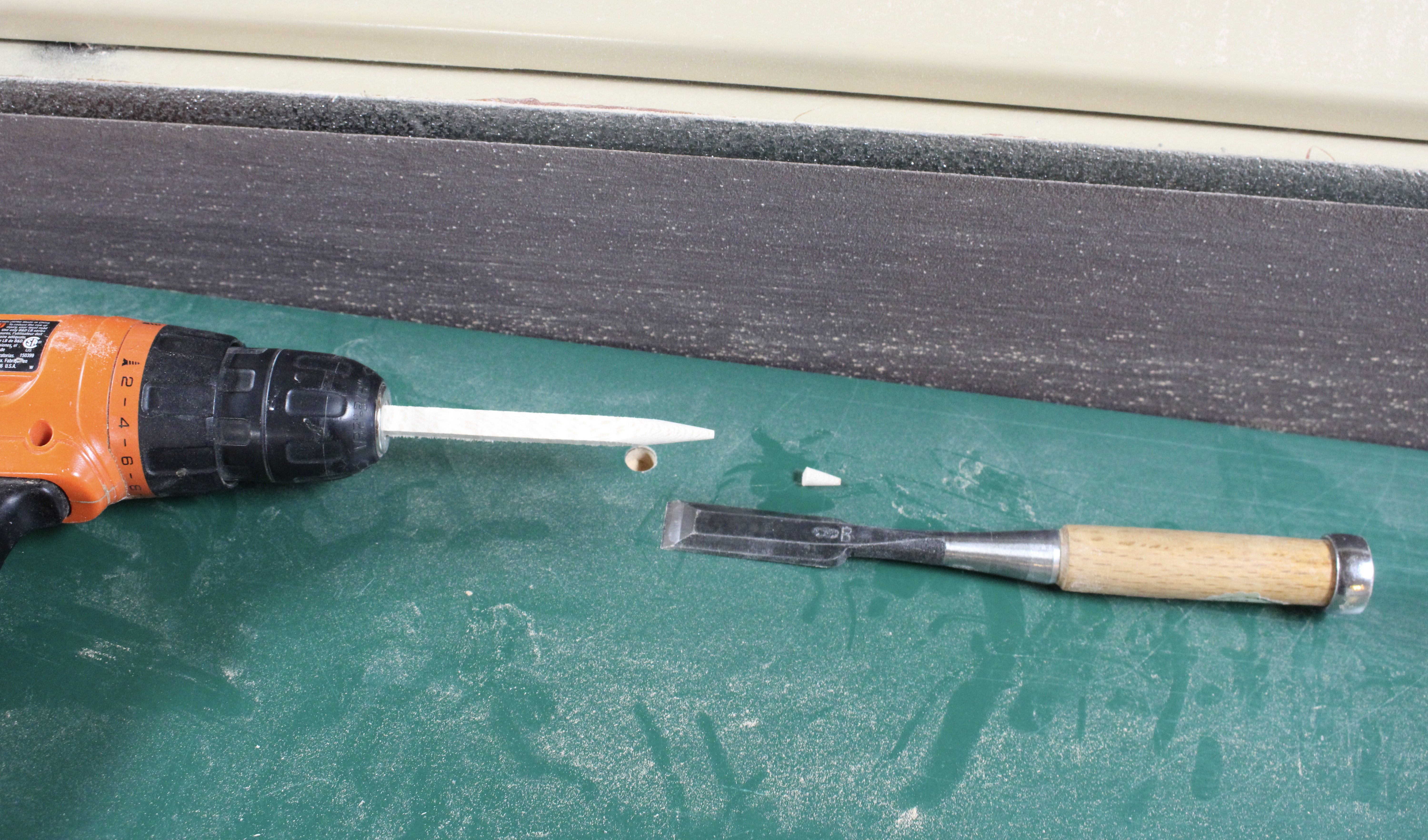
Then, the 5″ fragile end cut offs are put in the chuck of the drill with medium tightness, and sharpened to points. When they are about 1/16″ at the tip, a 1/2″ tapered plug was cut off with a sharp chisel.

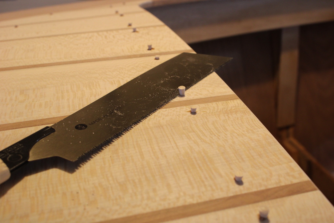
Each hole was filled by gluing a plug in place, tapping gently with a hammer. When the glue (Titebond III) dried, the plugs were carefully cut off with a pull-stroke Japanese saw, and sanded flush.

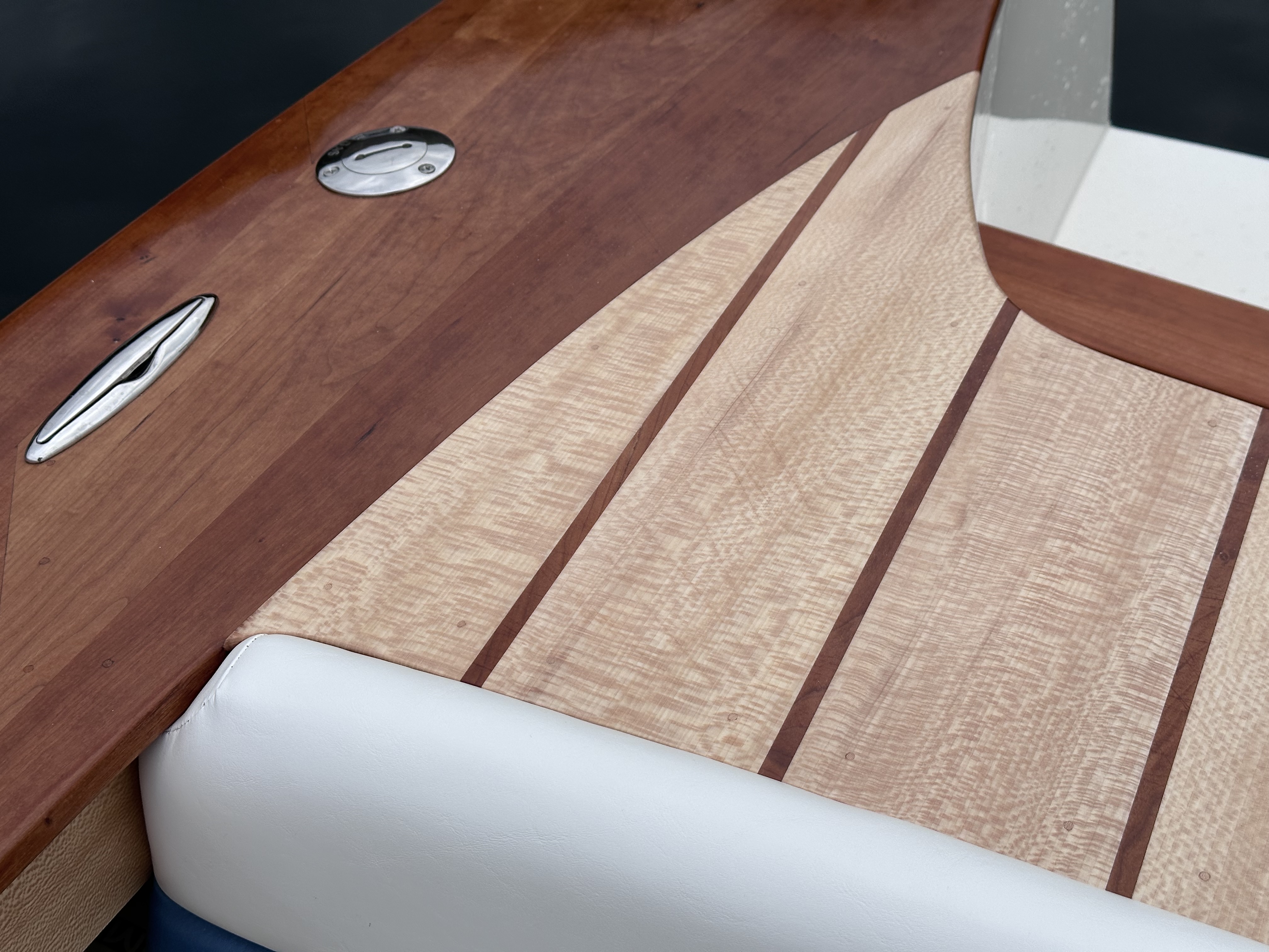
After varnish was completed, you can barely see some the face grain plugs, and the surprising figure of Quartersawn Sycamore.

Small face grain plugs are a detail often not noticed, but removing the screws prevents future corrosion, and 3/8″ plugs are not needed.

Adding 1/4″ Sycamore Veneer to the Boat Deck

The front deck was built with 1/2″ marine plywood as an underlayment for the 1/4″ thick Sycamore veneer pieces. Sycamore is a common wood in Indiana, but not highly regarded for furniture or high quality wood work.

It is not as hard as White Oak, Black Walnut or Hard Maple, but harder than Soft Maple and similar to Cherry. So, when I found a group of 4/4 Sycamore boards from the same tree that were perfectly quarter sawn, I couldn’t resist buying the lot.

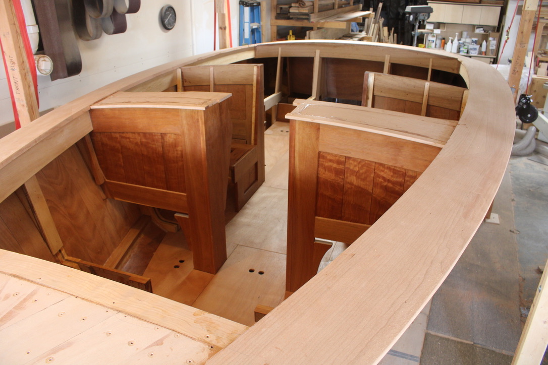
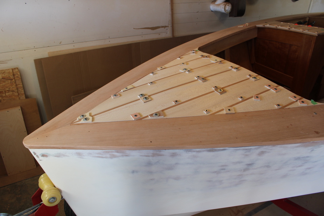
In preparation for the top veneer layer, I started with two layers of 3/8″ marine plywood as underlayment, which allowed for some bending of the deck contour, and some room for fairing. This can be seen below at the front.

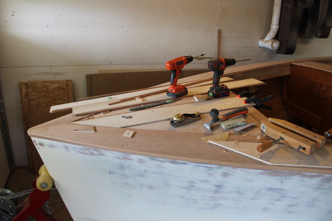
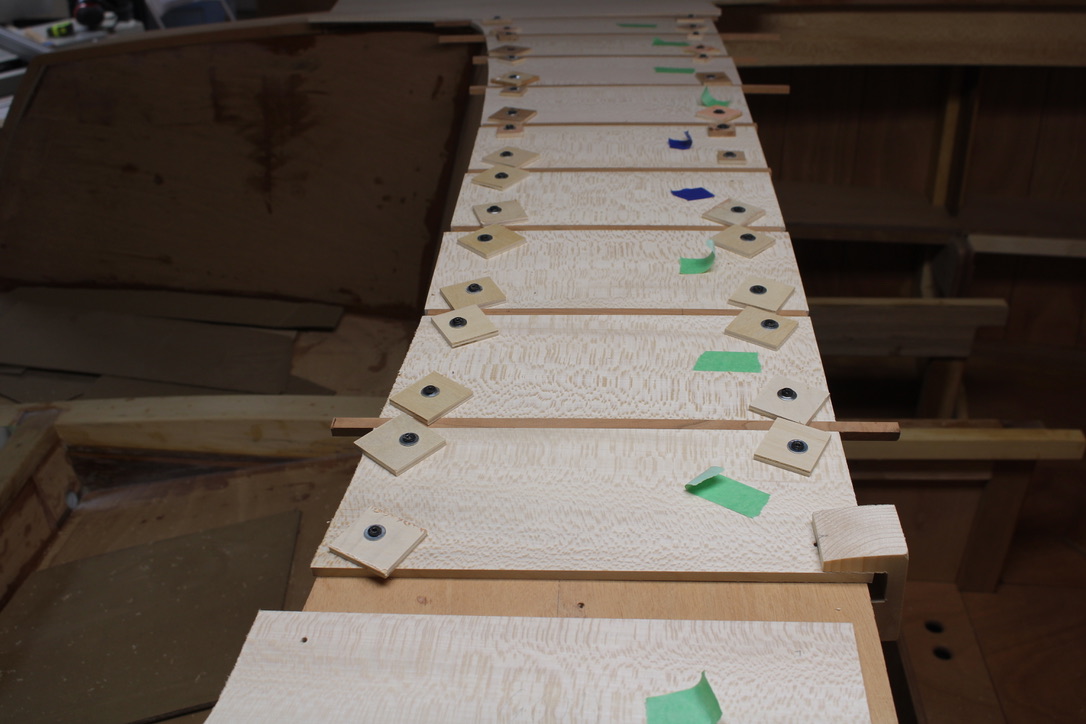
Then, I began with a 1/2″ Cherry stripe in the middle, and added the first 5″ wide Sycamore strips, rough cut and sanded as well as possible to fit to the Cherry deck trim. I pre-drilled 1/8″ holes to screw it down to the underlayment.

Rather than drilling a 3/8″ counter sink hole for a screw head and future plug, I used a wood spacer to protect the Sycamore veneer.

This is the cross deck behind the back seat, and shows the wood washer / spacers. After the parts were epoxied in place, I removed all of the screws, leaving only small holes.

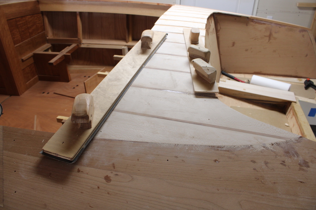
After epoxy and removing all of the screws, this is how the deck parts looked, ready for final fairing and sanding. It takes long sanding boards to smooth out the hills and valleys.

Next up is making some small plugs to fill the small screw holes.

Making an Angled Flange for the Navigation Light

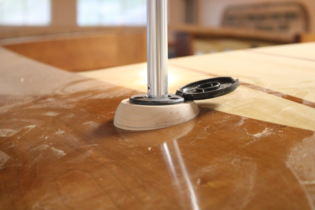
The best location for a stern navigation light turned out to be on the port side, where the top trim was angled down from level. I wanted the navigation light pole to stand nearly straight vertical. The two choices were using a hinged pole, or adding an angled flange before drilling the entry hole. I thought the angled flange would be the better look.

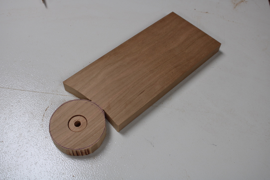
I started with a compass, drawing a 3″ diameter circle on a piece of the Cherry wood I used for the top deck. The first operation was to drill a 1/8″ deep starter hole, with a 1″ Forstner flat bottom drill bit. Then I drilled the center out with a 1/4″ bit to place a 1/4″ bolt through.

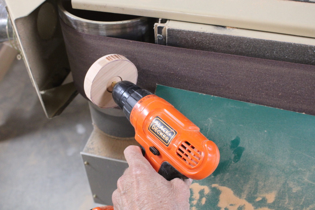
After band sawing the circle, I put the 1/4″ bolt through it, and began spinning it with my drill against the moving edge sander. It created a regular circle, and I added a pleasing round over shape on the top corner.

Then I finished drilling the 1″ through hole for the post, and sanded the base on one side of the flange until it gave a good vertical position for the navigation light.

The mounting sleeve with cover was rotated to the best vertical angle, and screwed down to the deck. This bother is a detail that doesn’t get noticed often, but still satisfying. A sideways leaning Navigation Light Pole would always be noticed by some, and not considered right, if only by me.