Routing Detour

A two or three year boat building project invariably gets interrupted in all sorts of ways and the current detour is a desk I am working on. I was cutting the dovetails for the drawers, with my special dovetail routing system. It usually starts with cutting the tails on the bandsaw. The plywood guide has a thin wood piece attached to the bottom that slides in the slot on the metal saw top. It is marked with 8 degree pencil lines to lay the board for cutting at the correct angle.
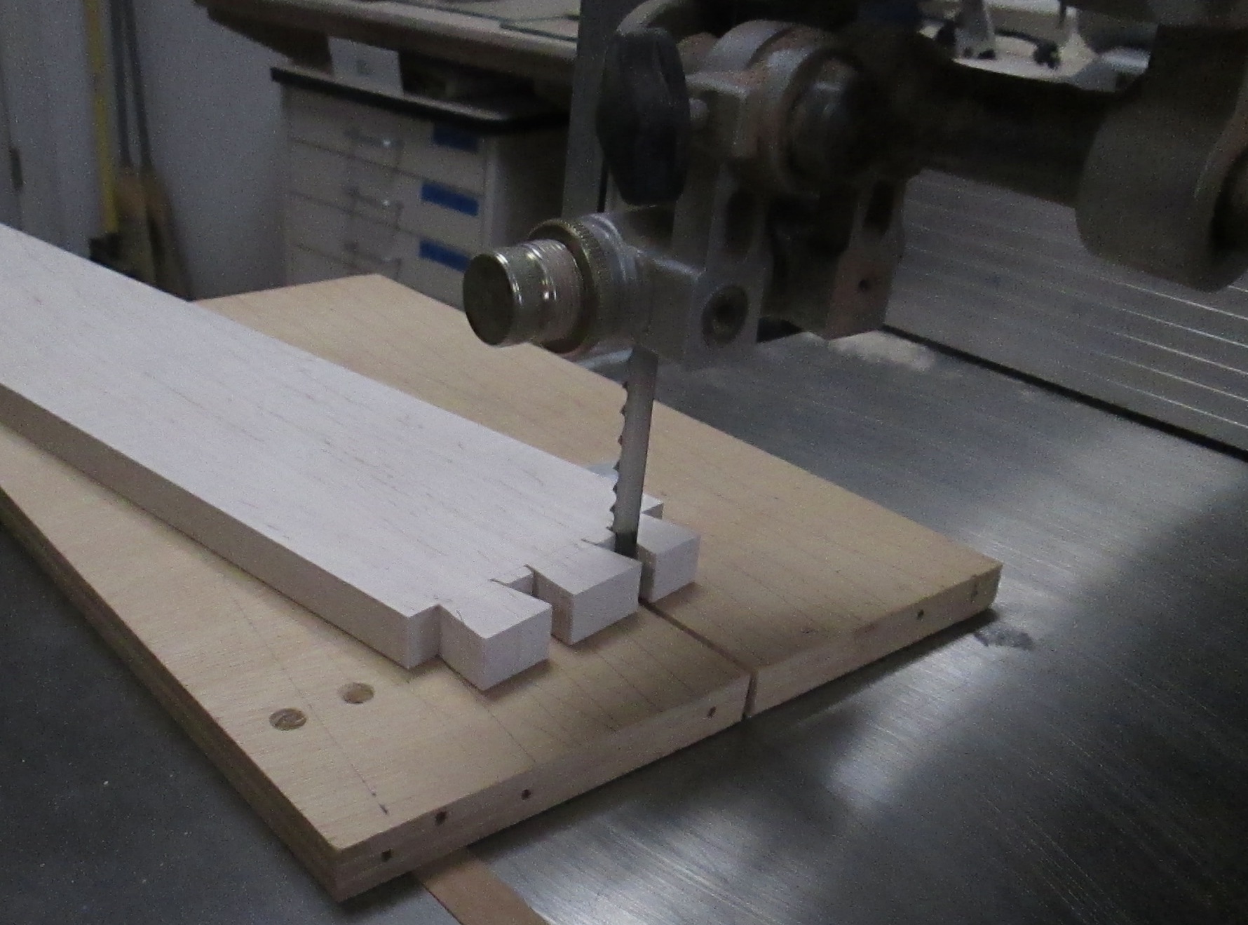
After the outer cuts are made, a little more work is needed with the bandsaw or chisel, to remove the waste between tails. Then, it gets clamped to the router jig for marking the pins with my trusty pocket knife.
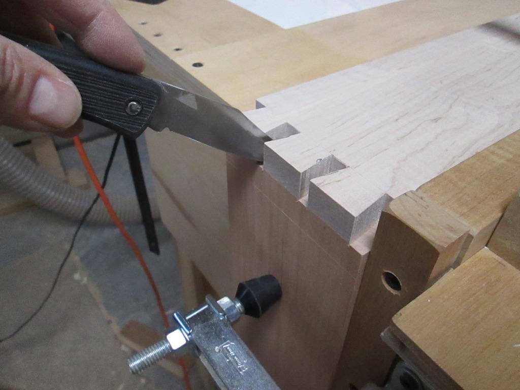
After that, it is moved to the front of the jig, and clamped flush with the top.

The sliding table sides are moved exactly to the pocket knife marks (not easy to see here) and clamped in place.
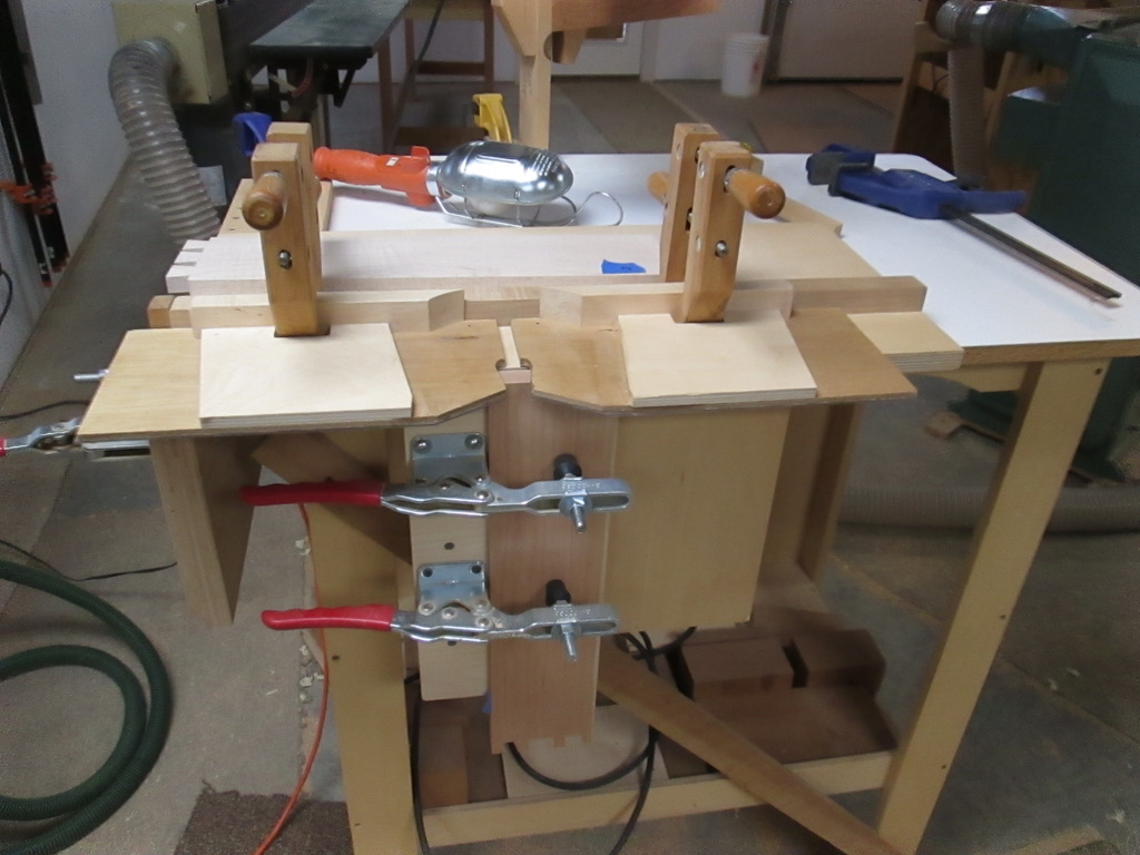
The router is then set to the correct height for the width of the drawer side, and it is ready to roll. Normally for through dovetails, I cut all the way to the back fence. 
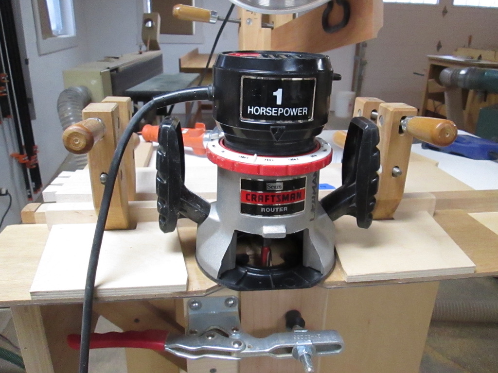
If all goes well, the router does a quick and accurate job of taking out waste.

Checking the fit should look like the example below, and quite frequently does.

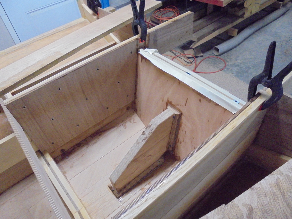
When I want the dovetails not to be seen as on the front of some drawers (half-blind), I use a spacer against the back fence to stop it short. It was going well except for one cut, and I forgot to put in the spacer to limit the router travel. Of course, this was the last step in the drawer construction, and of course, it was the last drawer corner I was cutting. 

Haste makes waste, and when I felt the router going all the way to the back of the jig, I knew I was in trouble. Sure enough, I routed right on through the drawer front, making the big hole below. 

I considered starting over but didn’t have the right size wood, the time, or as I heard one college summer in construction, “It ain’t a church.” Angled or curved repairs are much easier than a square cross grain fix, so I had to look carefully for a scrap piece that had some end grain to match pretty well.

I bothered to fit the piece as well as I could to line up the grain. After gluing and sanding it flush, it disguised well enough not that I decided not to mention it to my “client,” my grandson. He had been helping build the desk for himself, but was not present at this step. 

I rather doubt if he will notice the repair right away. But, some day when some random thing goes wrong for him, I will ask if he has noticed the mark on the drawer front. 

Now, I wouldn’t trade the drawer for a perfect one. It becomes the enduring story of how life goes, when what was hoped for does not happen, and must be worked through with creativity and perseverance. It is a life lesson waiting to happen . . .

Inner Trim Line

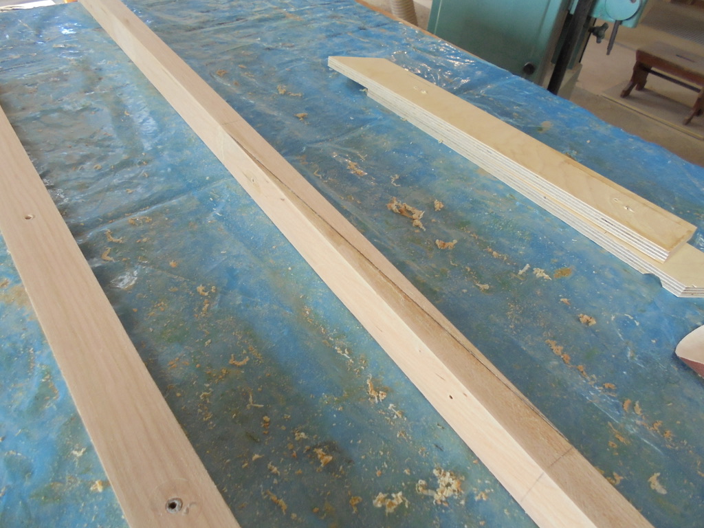
The outside deck line is created with the 1″ x 1.5″ long molding called the sheer line. The next step is creating the inner trim line which defines the deck and the seating space. The blue tape seen below left is first visual experiment.

For the molding, I picked a 12 ft. piece of straight grain cherry. Granted, it is not the world’s first pick for boat building wood, but it is available, of medium density, and works superbly. I also had plenty on my wood rack so I decided to “shop local.”

To make a 22 ft. continuous molding, I had to splice two pieces with a 20 inch long scarf joint. It goes the full distance of the paper below. By making it long, it allows basically the same bending characteristics as the other solid pieces.

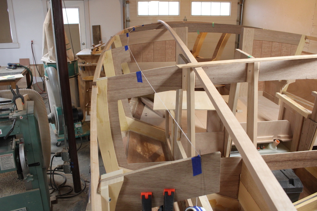
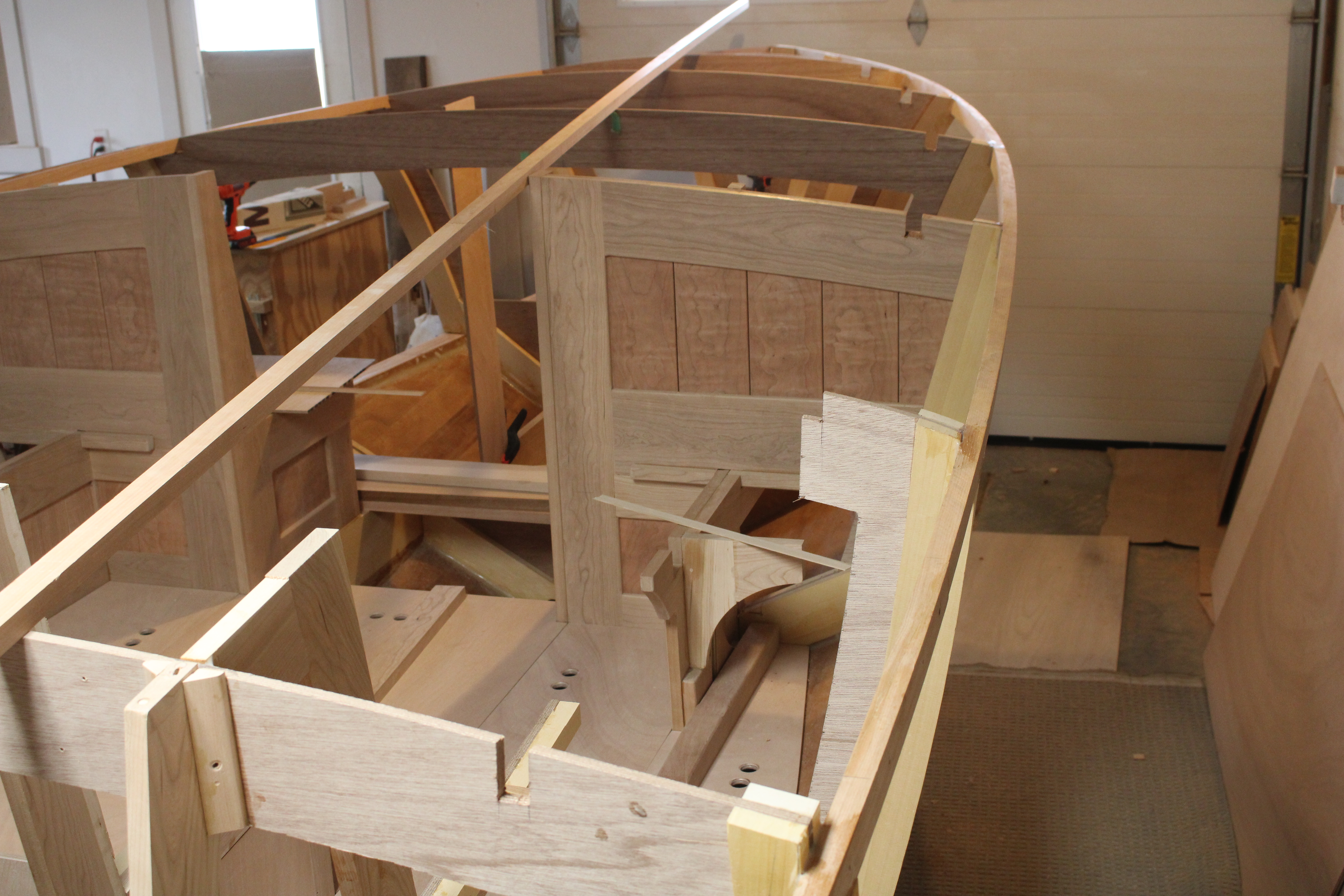
The left side is shown with the long molding ready to install. The nails and string show the refinement of the line, and allows a visual inspection to see if it follows a regular or “fair” curve.

It passed muster and served to position the cutout notches. They were cut with a hand saw, chisel and rasp, as needed to seat the molding the right height and along the curve.

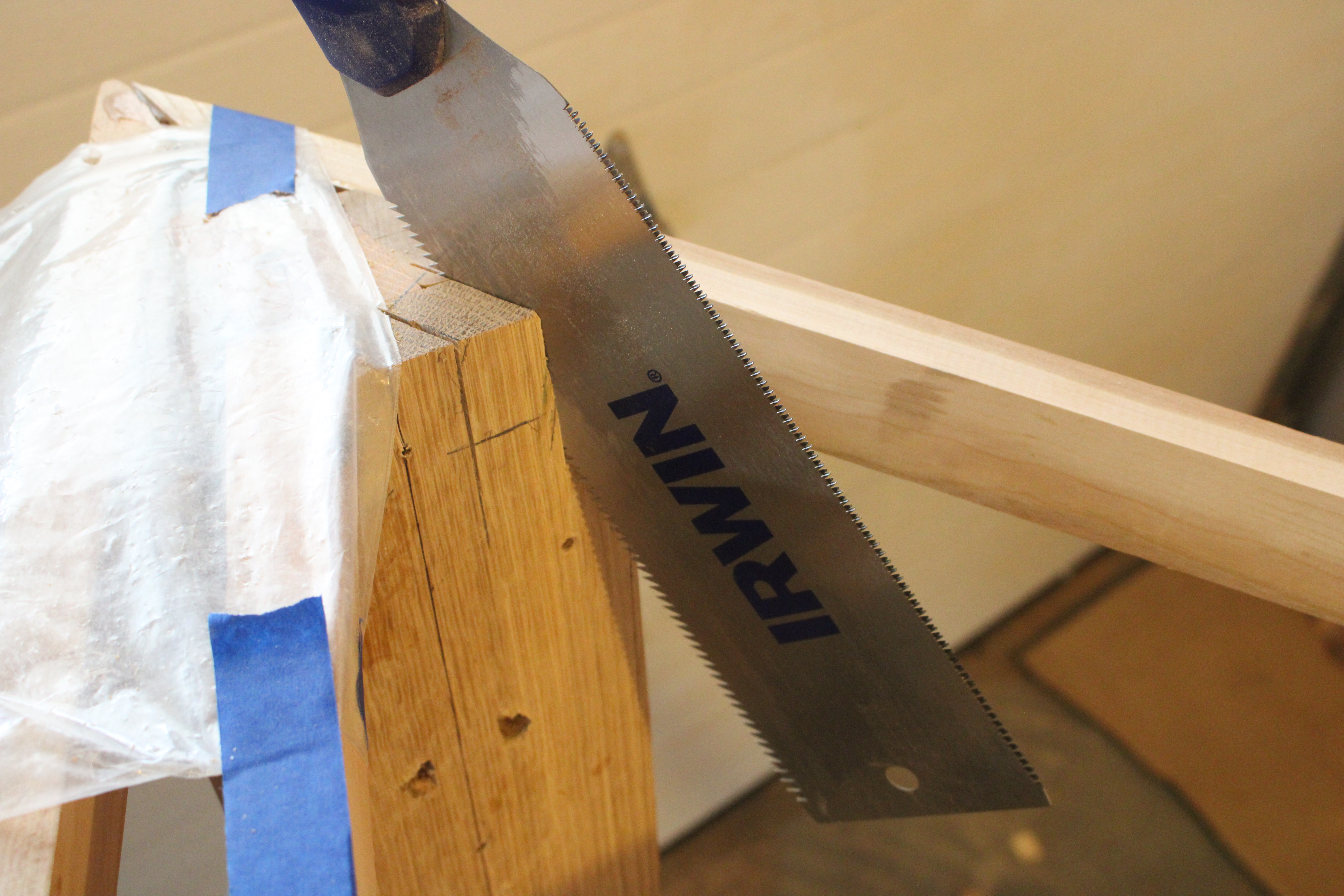
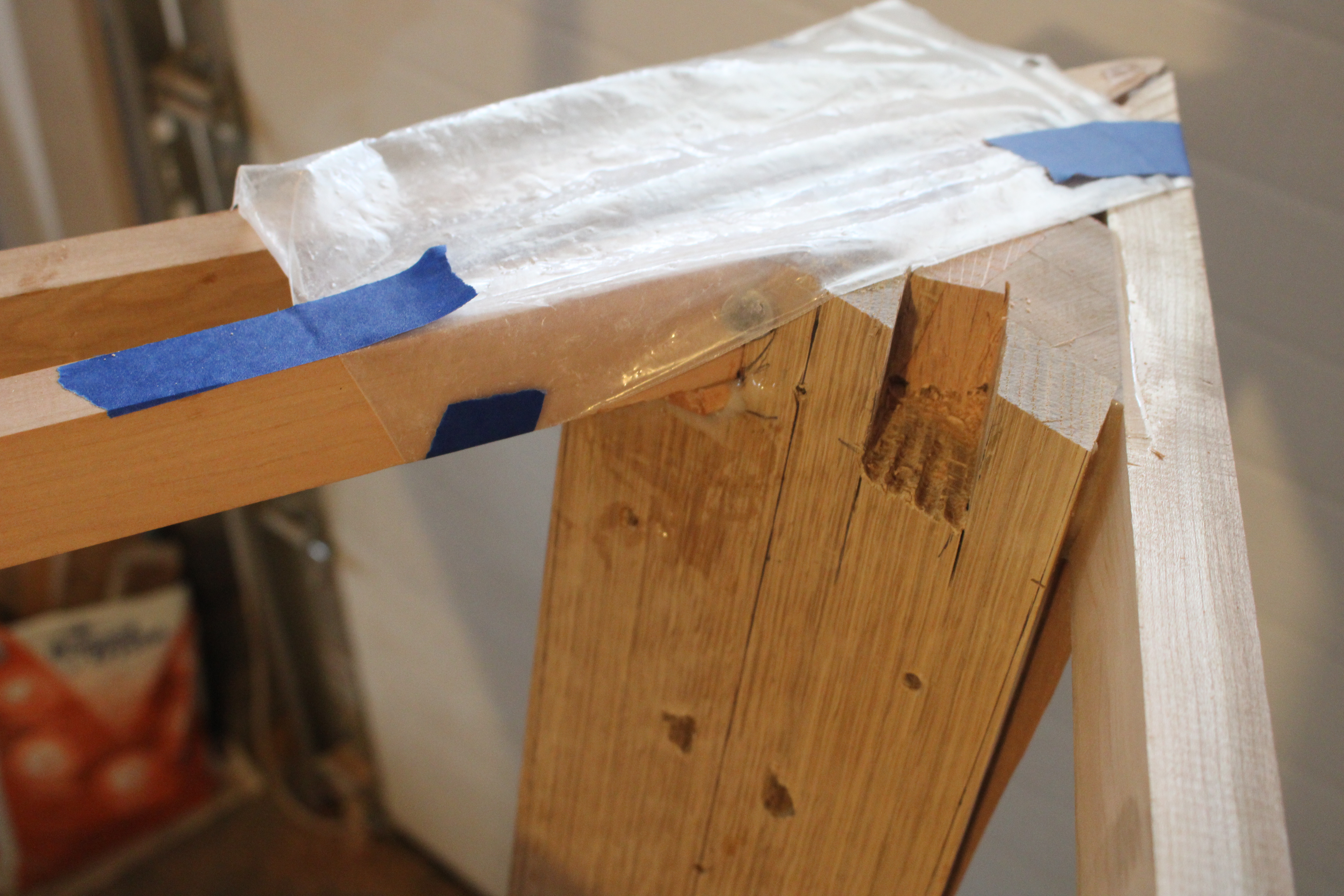
The most difficult notch was the front, which did not go all the way through. I cut as far as possible with the Japanese pull stroke handsaw (bought at Menards).

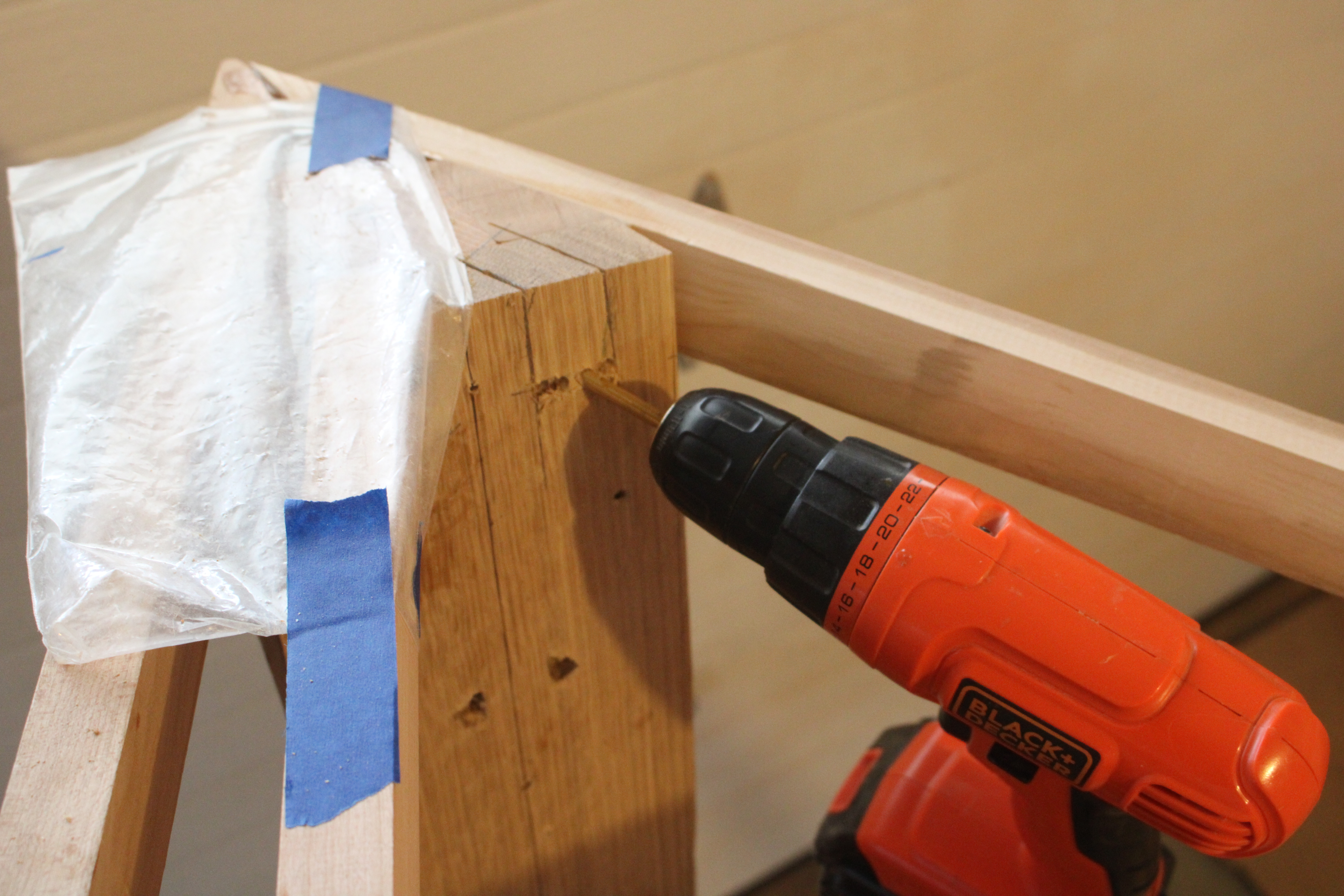
Necessity is the mother of invention, so I figured the drill might do as well as hammering with a chisel on the white oak front frame.

Then a bit of the easier vertical chopping to take out waste.

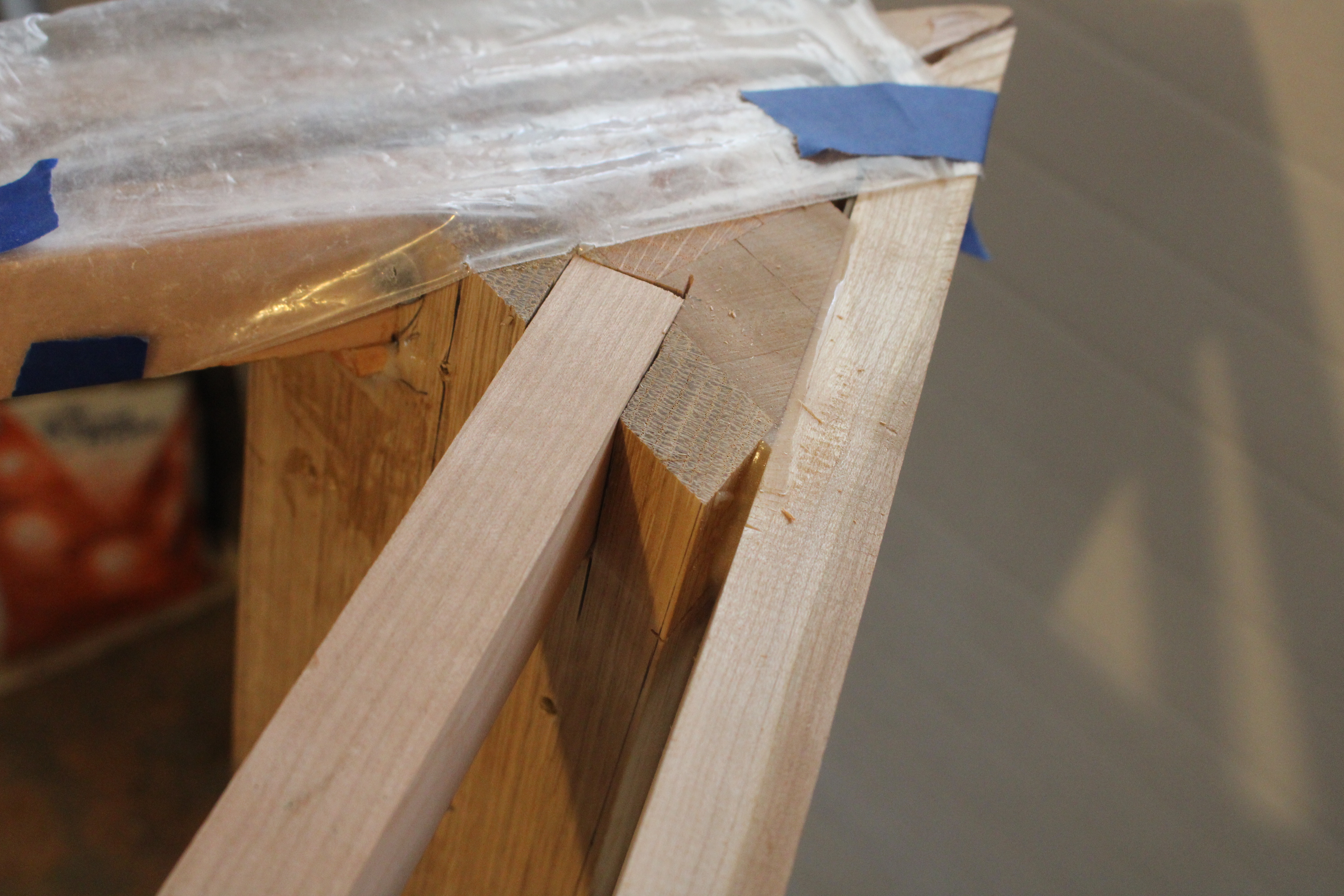
And the half mortise was ready to final fit.

After the curve of the entire runner was micro adjusted to suit the eye, it was bent into the notches and bonded with epoxy. It becomes a visual line and a strength element, and the structural organizer for all of the interior spaces.

The umteenth step of the impossible journey is done but a seemingly endless list awaits. Tomorrow . . .
Curves and Corners

From the beginning of building a boat, a grand attempt is made to follow plans, if you have some which I do not, and keep both sides symmetrical. That applies especially to the level, straight and and flat parts.

But the most visible and beautiful lines on a boat are at the edges, on the side, and the transom end. Those are mostly curves that are not so easy to measure, so the eye makes the final judgement on whether a line looks fair and pleasing.

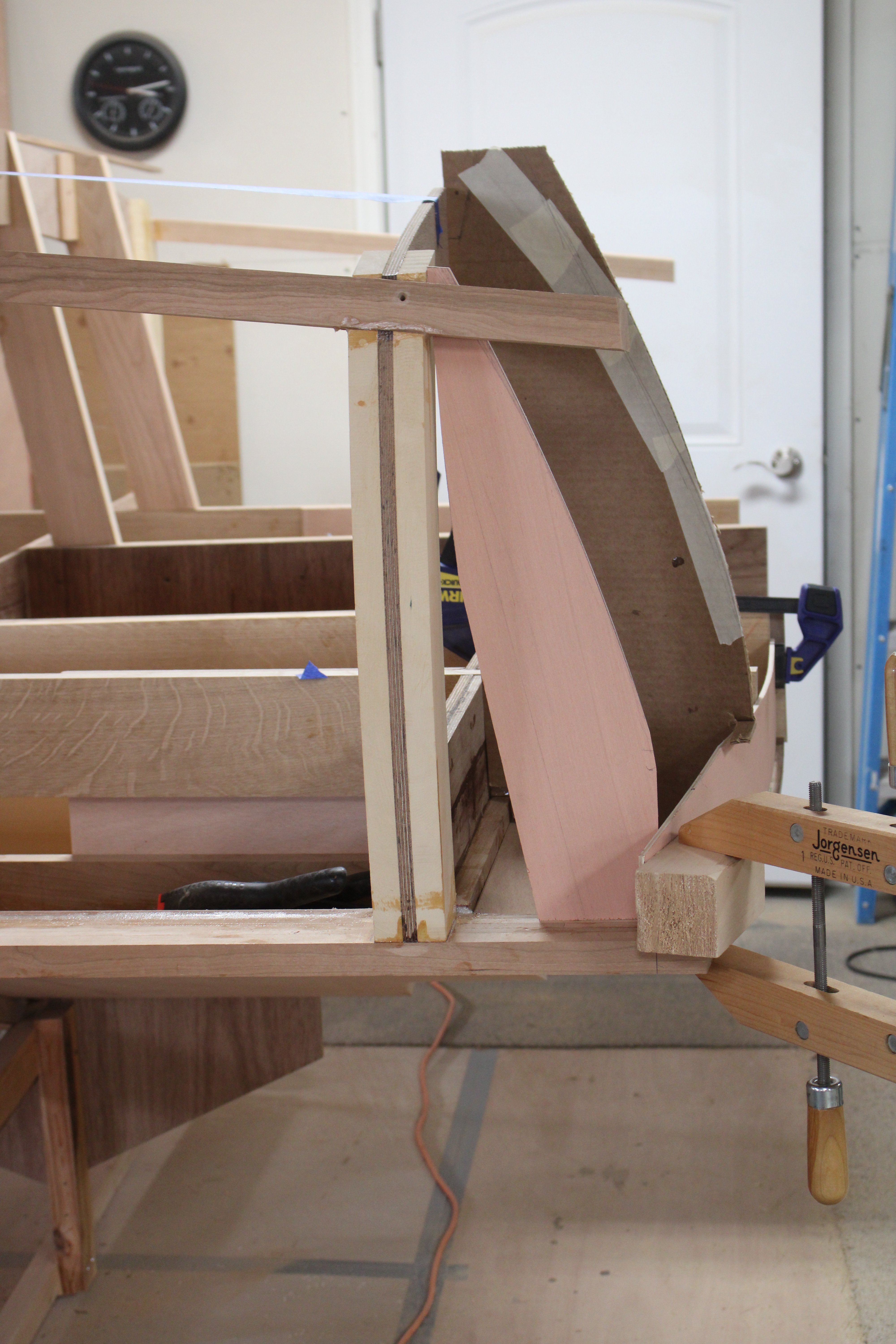
This time it was figuring out the outer, lower curve of the transom. As usual, it starts with a pencil on paper. Then, I often use a thin bendable stick, shown at the bottom, to visualize the full size 3D shape.. Below, the bottom pieces complete the line, and compliment the top deck edge molding (sheer line), in smooth symmetrical curves.

Here is the side view of the full size cardboard and 1/4″ plywood patterns in preparation for the curved back corner lines.

Admittedly, the wooden boat building world is small, but when I hear of another builder, I like to meet and discuss construction ideas with them. So, it was my pleasure recently to be introduced to Charles Onyon, who has an interesting resume’ including working four years at Van Dam Custom Boats. A few years ago, I visited and took a tour of their inspiring shop, likely the premier boat building company in the country.

Charles came over to visit, and gave a far more educated scrutiny of the boat than the average house guest. He knows boat building including wood types, joinery, paint selection, and engineering for strength and esthetics. He is smiling because most people don’t know he is a celebrity . . .
Boat Hull Strength

Building a boat from scratch creates the continual question of whether each new step of construction is going to be strong enough to hold it together against the forces of water and trailer transport.

Two main bottom runners go from the transom forward past the cockpit, and two side runners go up half way. The fiberglass fabric epoxied to the hull also adds stiffness, but at the front and back, it needs support points that are strong enough to lift the boat up.

At the back, white oak beams frame the inner transom, and the slots were cut to add side boards.

Next, the side beams are added over the side hull runners, and upright posts are made to tie the back beams to the cross frame and seat structures.

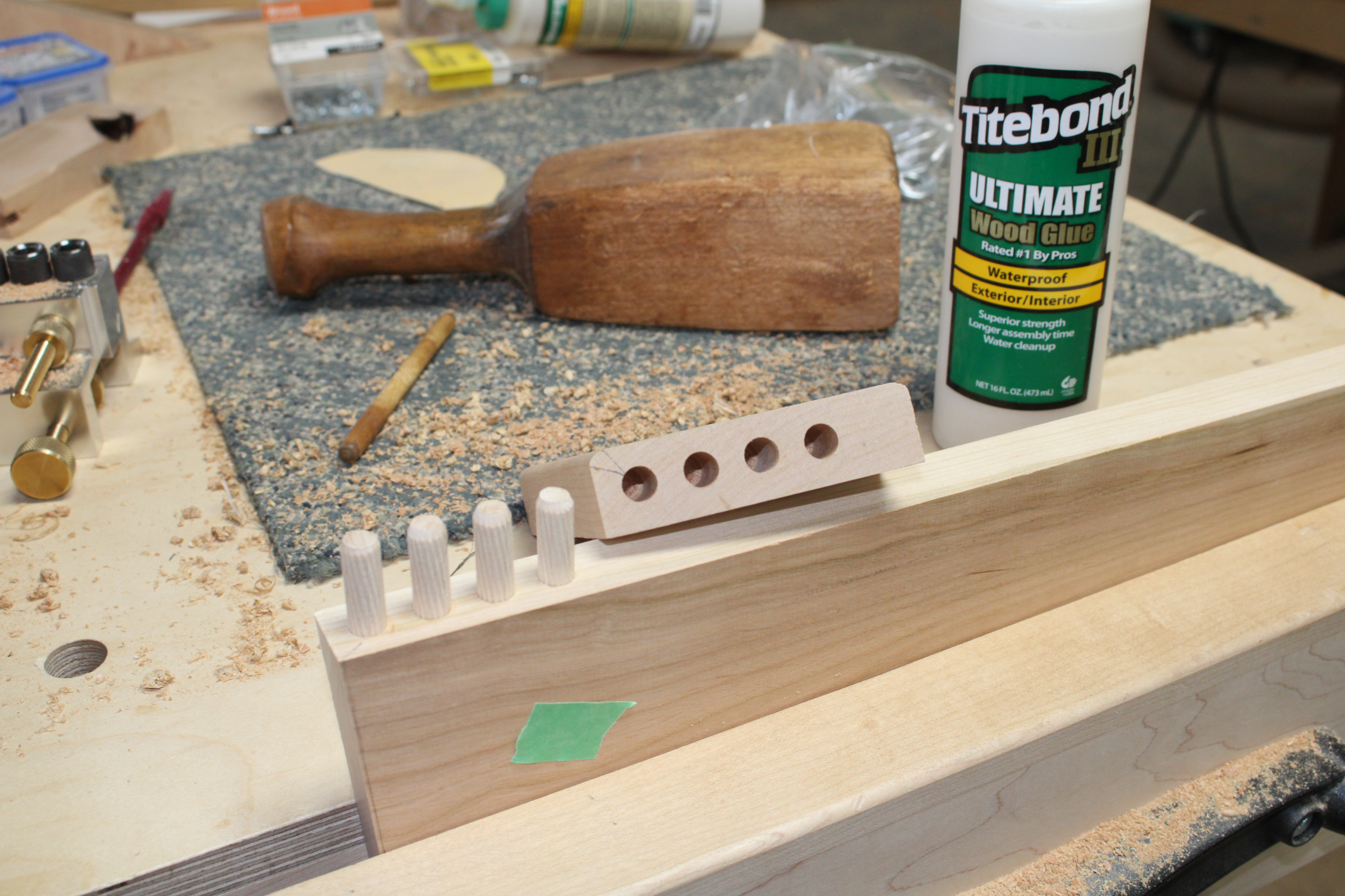
As usual, as many joints as possible are strengthened with dowels.

The dowels will never be seen after this step, and much of the beam framework will be hidden behind the seat or under the floor, and may be taken for granted. But if you ride in the boat, and you return to the dock alive, you may assume the engineering and construction made the grade. What’s inside a person floats a good life also.

Boat Seat Framework

A long project like building a boat is very hard to keep perfectly on track, especially as it does not create the discipline from a regular work week. True to form, the boat schedule broke down and did not reward me with much valuable photography or writing material. But sister Mary, in her gentle way, reminded me that I did not make the deadline last week for my blog post, or perhaps now going on a month. So, this is for rebuilding momentum, and Mary.

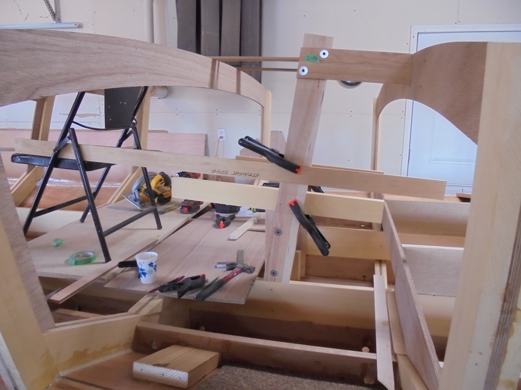
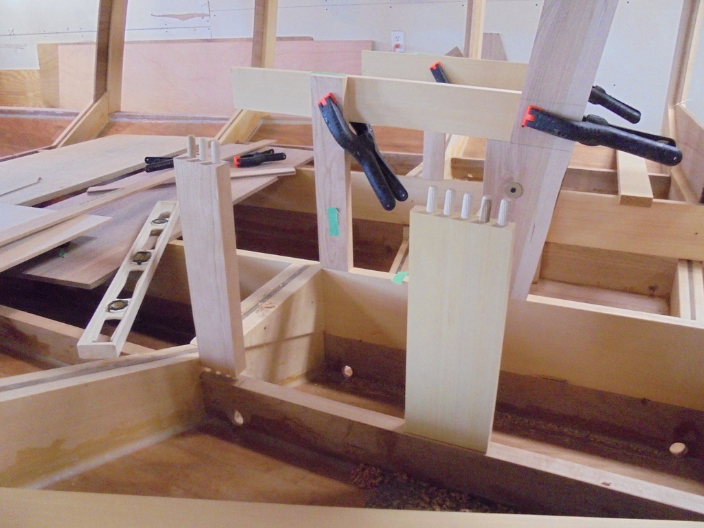
A drawing finally emerged, with help from Jeff Margush, as we imagined what the stern might look like some distant day from now. The photo shows a lot of disorder, coming from rebuilding the back seat supports, after having already glued them in place once before.

At that point, you have to take the saw to the problem instead of the piece of wood to the saw. I made a saw guide which was screwed on the leg assembly, and waxed it well so the saw slides freely. A few times climbing on and off of the boat for things forgot finally got the cuts made and a check off on the things to do list.

The boat a bit like a 1000 Piece puzzle, with out any picture or directions, made more complicated by some redo operations. It seemed that a slight angle would be more comfortable for the back seat drivers.

So far, I have used dowel joints, biscuit joints, and tongue and groove for hull planks. And now to hold up the two extra seats behind the captain’s bench, I used a cross lap with a support bracket. The seat will be a piece of 3/4″ marine plywood, which will also be stabilized by resting on the divider wall ledge. The long seat board extends forward and becomes the center support for the front seats.

The curly cherry also suggested that it be presented in panel areas where it will be seen, instead of common marine plywood. So I acquiesced and have started using the wavy, bubbly variety. It was one of those pieces of wood that the normal furniture builders who frequent Nisley and Sons east of Goshen, Indiana did not want. The uncommon wood goes to stand in a corner for people like me to investigate. When I saw the curly piece, thick enough to split in half and book match, I brought it home.

3D Boat Shape

The end of the story from the last post is shown below, as I am tuning up the final angle where the sheer log meets the bow. It may look simple enough, but hanging on to a screaming body grinder at a precise angle with 36 grit paper is no casual task. I could have used a saw and a file, but, if the edge is visible and there is room to move, it is the fastest and most direct path toward completion.

I have long wondered what built by hand means, but if it is anything beyond shaping something strictly with your fingers, then this concentrated, practiced effort has to qualify also. Taming the body grinder is on par with training our Boxer dog Buck.

He never was fond of the leash, and pulled continually toward the next interesting scent or dead treasure. We always had to be prepared for the surprising and potentially injurious jerk, should any rabbit or any other animal jump to flee.

The grinder can be a lot like that dog. It pulls, it whines, it catches and jerks, all the time requiring it be handled with gentle pressure. But if it is mastered, it pulls as hard and fast as an Iditarod sled dog.

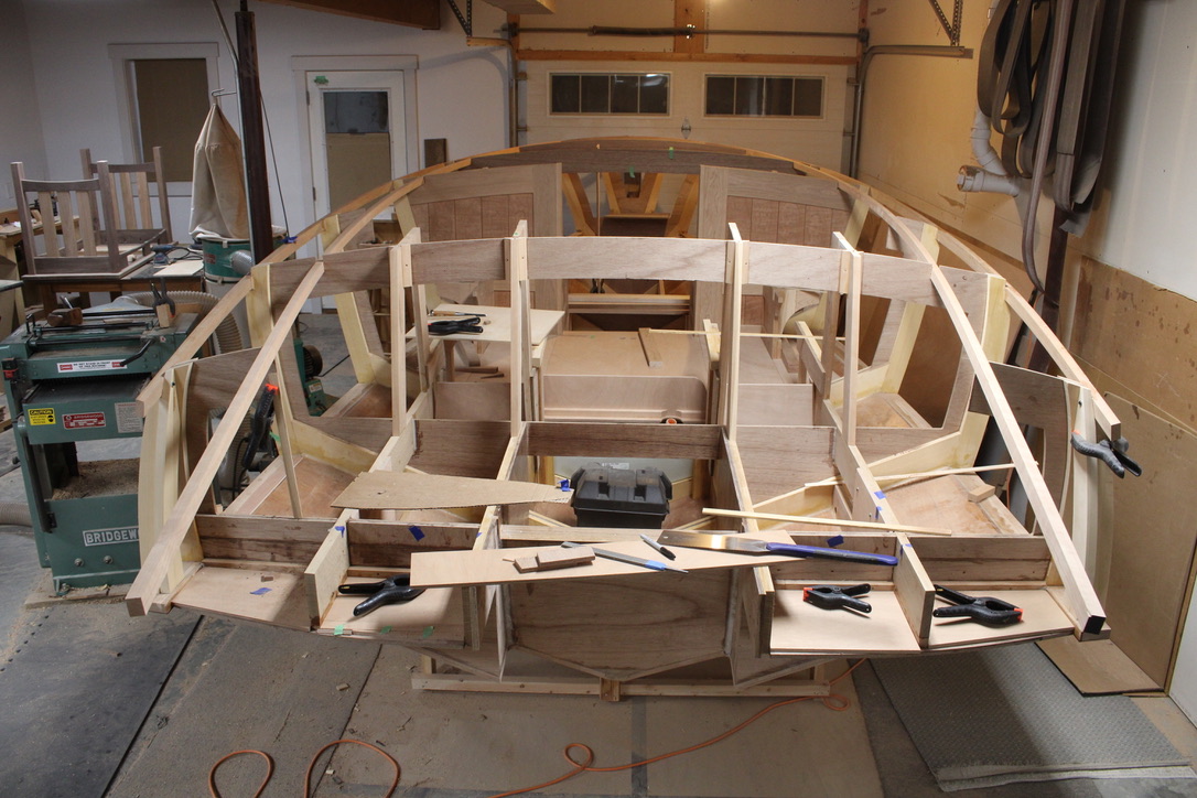
Those long sheer logs or moldings are now faired, and assembled into the framework of the boat. Now, it allows the imagination to go down the road a ways, as the 3D shape is coming into view.

Tough Transom

The next up assignment is making sure the transom is strong enough to hold a 500 pound outboard motor under working conditions. That also means all of the railroad crossings and the normal Indiana roads. The transom itself (taped off) was made of 5 parts of 1/2″ marine plywood, laminated with epoxy.

Next, an inside corner brace was added, made of four laminations of marine plywood. The outer trim edge was dowelled and epoxied to the core.

Then I epoxied the triangle to the boat keel and the transom. On the surface, I added fiberglass fabric, embedded in more epoxy, which connected it all together with much more strength. Notice the gray corners which are epoxy fillets, for even more durability.

Some times I try to imagine what kind of stress or blow could actually do harm the the part I am working on. I would love to see some strength testing on this piece of work, but rather than waste the time and wood, I go on with confidence. The last boat is seven years and still floating . . .
Sheer Magic

The line where the top of the boat meets the side is called the sheer line by traditional builders. It is never straight, and is a defining shape of the personality of the boat. Sometimes it starts high in front, to cut the big waves, and comes down in the middle perhaps for rowing or fishing. This beautiful rowboat shows that reverse sheer.

My speedboat on the other hand, will not be battling such severe weather, but will need great visibility forward at all times. In this case, it has a positive sheer line, lower at the front to see across, and higher in the cockpit area for seating comfort and wind protection.

The line always curves inward toward the front, and the whole shape must be “fair,” a beautiful shape. Fairing a curve means making the shape flow with out hills or valleys. Lumpy does not make a winner. The best help for a good curve is a slender board long enough to go the full distance, thin enough to make a consistent bend, and thick enough to resist distortion between supports.

I chose a piece of cherry, and sized it to 7/8″ x 1-1/2″, and then had to splice together 2 twelve foot pieces to make 20 ft. As noted in the last post, the first one broke under the pressure of bending. I picked a straighter grained piece, thinned it a little, and started over. Below is the scarf joint, angled over 14″ so when glued, it will behave mostly like a solid original piece.

Then, the process begins by cutting a notch at the corner of one cross frame, and gradually fitting the sheer log in place. The photo below shows starting in the middle, using a bungee cord to hold it and then going on the next frame. Not a step to rush, as it will be examined, praised and criticized ad infinitum should this boat ever get on the water.

My friend Stan Oyer asked if there is a point in boat building when you have to give up the tight tolerances of levels, angle guides, and tape measures. Yep, and this is another of those many times. Below, I spring clamped two straight sticks to the extended sheer molding, just to see if the angle is similar side to side. I did not measure, or level up, but just got back and looked at the two sides from a couple of angles. My conclusion is that they are beautifully compatible, if not perfect.

On to the seat framework coming up . . . You are never lost until you are out of time.

Back Seat Framework

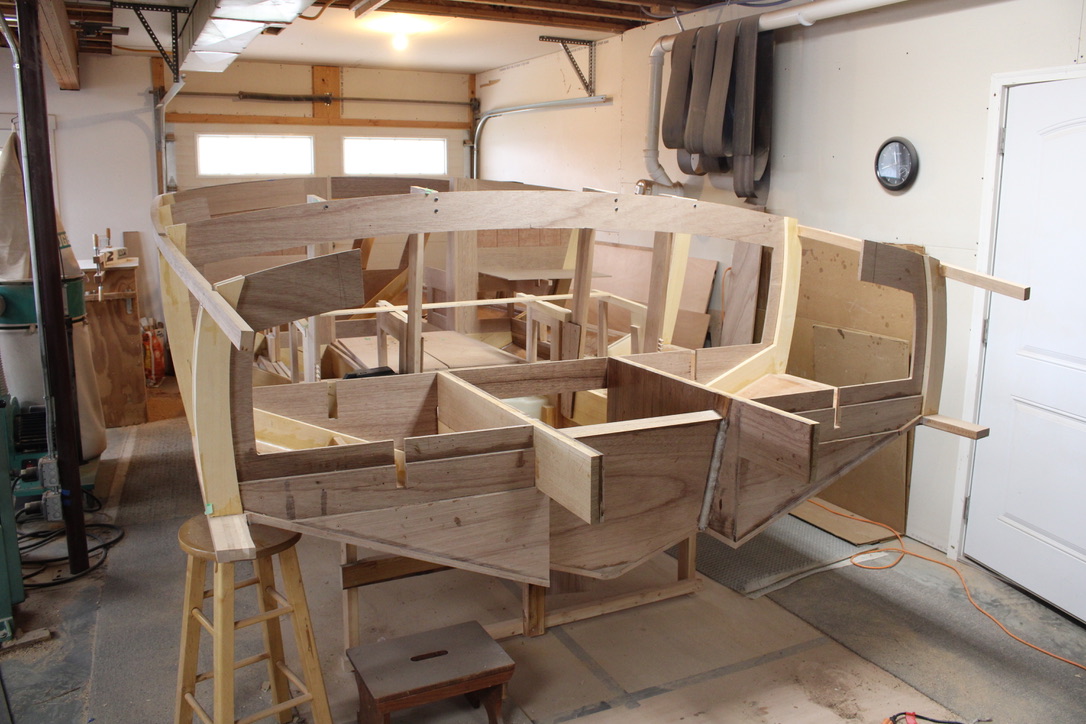
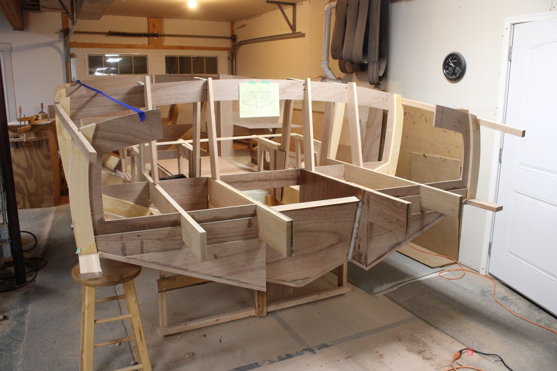
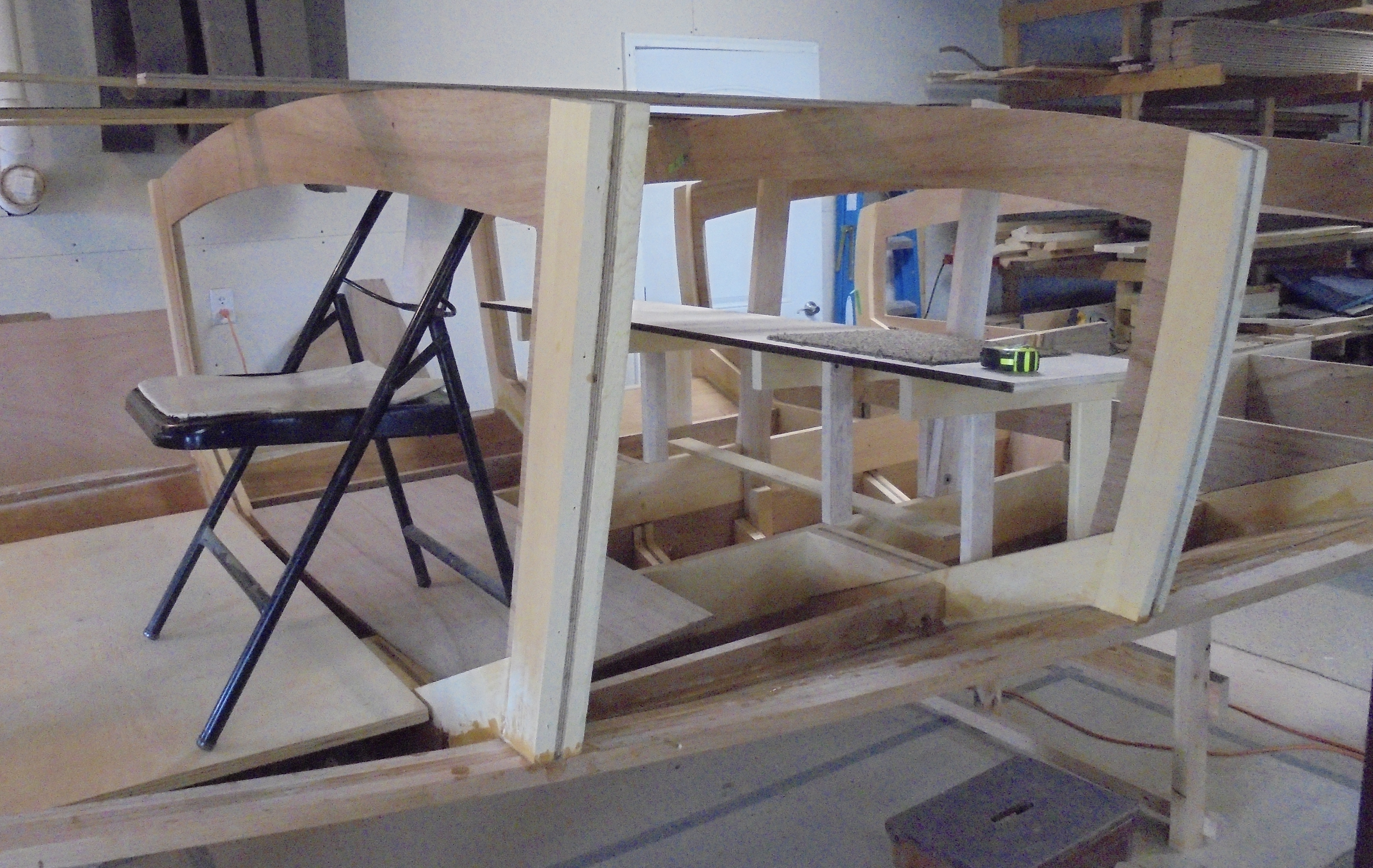
The hull inside is now strengthened with epoxy fillets and fiber glass cloth, and it is time to start building the seat framework. To give room for the motor well, I started the back seat one foot ahead of the second cross frame.

The wood frames are easy enough, but making them comfortable, in a well planned layout is the most important goal of the present. Notice the chair, with a straight edge on the seat, which was my pattern for setting the angle for the bench. The back of the bench follows closely to the angle of the seat also.

This is not a couch to slouch back and watch TV. It is an upright posture to interact, talk maybe, and be prepared for hammer down on occasion. Once the mockup is complete, it is time to get out the trusty dowel drilling jig and make some holes.

The dowel strengthened joints will be another long lasting part of the boat construction. All the way along, I am thinking how I can build the current part in such a way that it does not become the weakest Link.

Below the four seat frames are dowelled and assembled to the boat longitudinal frames. The cross frame top over the seat will eventually be cut out, and moved behind the seat for more support there.

Next, layout for the front seats begins. A complicating factor is the possibility of two flip down seats behind the driver and copilot. It’s a fine line between ample personal distance and wasted space, as this boat is intended to have short run seating for eleven.

There’s plenty to be nervous about on the things that need to be figured out on the fly. I do prefer to get it right the first time, not like the sheer moulding I rebuilt today. I didn’t think the small knot was a problem, but the extra pressure needed to bend the moulding into the sheer line cracked it. I guess it was the weakest link.

A couple of hours on a repair detour and we are back on track. You are not lost if you are not out of time.

Fillets and Fiberglass

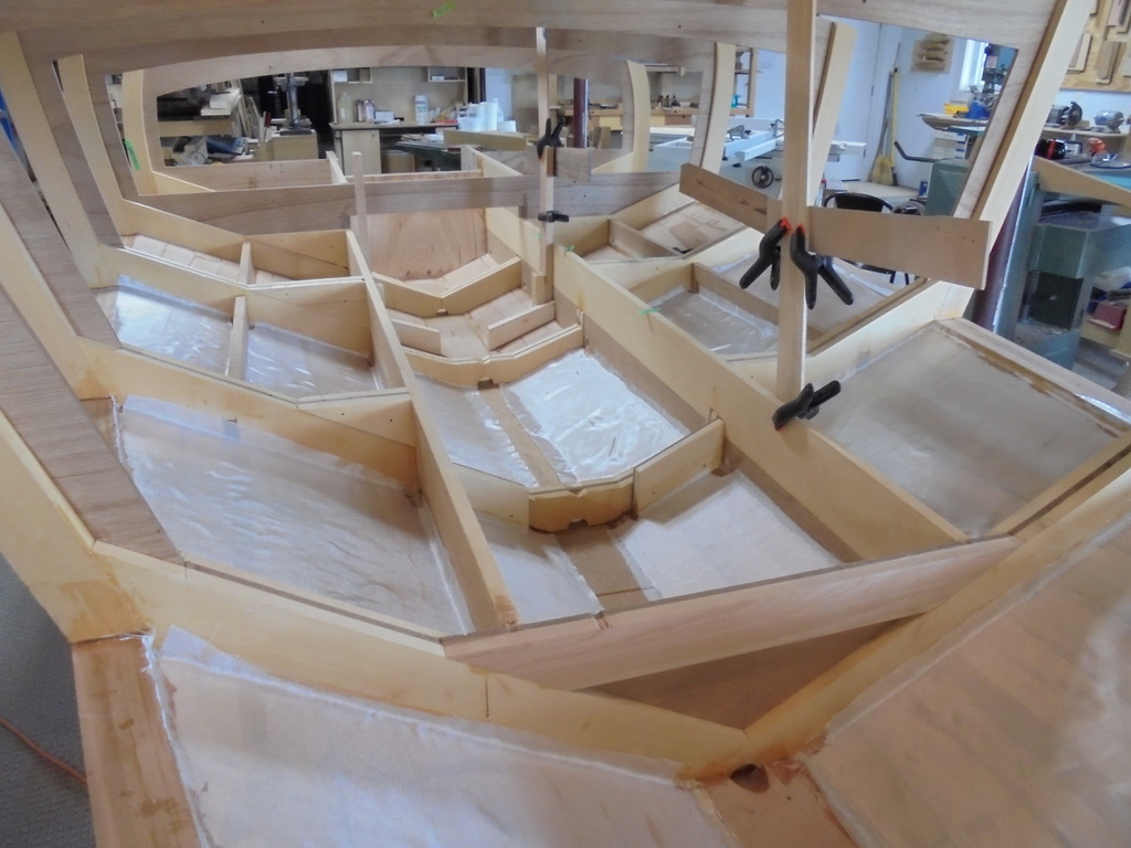
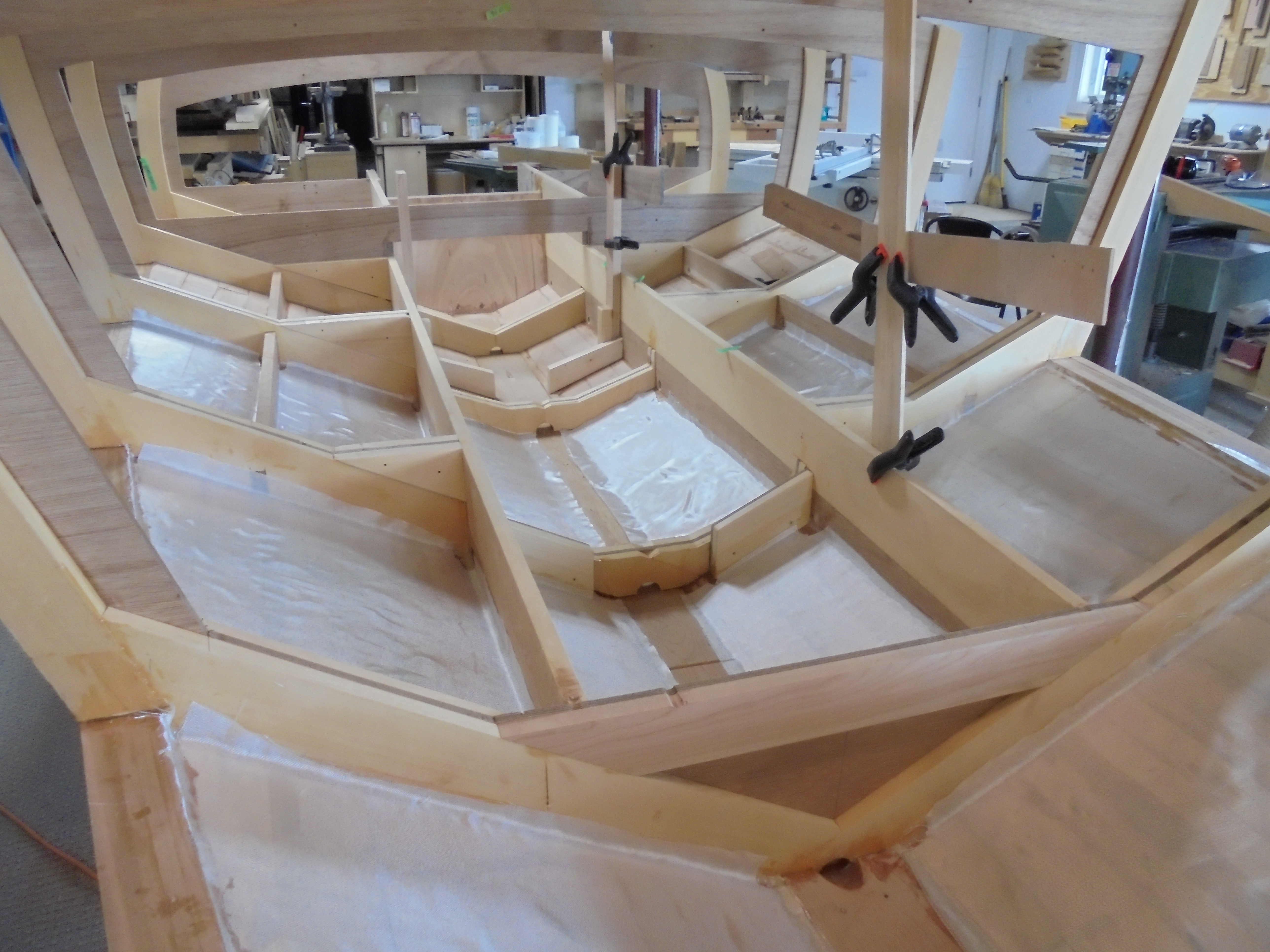
With the boat turned right side up, it is time to strengthen the joint between the cross frames and the hull planks. Epoxy is a wonderful sculptural and structural adhesive, and can be mixed with a variety of fillers to make more of a paste consistency. This can be a sticky mess, difficult to make it go where I want.

So, I put the thickened mixed mess in a Ziploc bag, and cut a small corner cut on one end. As far as I remember, this is similar to how my mom used to do some special decorative frosting on the cakes of our childhood birthdays. By the way, sister Anne reported that mom would have been 95 yesterday, had she not passed away at age 45. I think she would have liked to see my boat frosting.

Then, I inject a bead into the corners, as consistently as possible. When shaped with a round nosed plastic tool, it hardens without drifting into a reinforced epoxy fillet.

The next reinforcement to the hull is to add fiberglass fabric into each of the bottom sections. When possible, the pieces are cut to wrap slightly up the sides, covering the epoxy fillets. This serves to further strengthen the frame to hull joint, but also stiffen the tongue and groove plank layer of Okume marine plywood.

When a coat of epoxy is applied to the fabric, it wets out nearly clear, and becomes a strong, durable, scratch resistant surface. As the glass fabric and epoxy are added to the outer surface, the hull will be a super strong composite of the plywood core between the E-glass layers.

The boat is making forward progress but the amount left to do is sobering. This must be like hiking a middle section of the Appalachian trail, where you have gone too far to turn back, but still an unimaginably long way from the end.

However, Aunt Marge Liechty recently sent a particularly encouraging note, which was a kind wake up, keep moving call. It is time to make another detailed list of little things to do, step forward to do them, and mark them off the list . .