How to Apply Fiberglass Over Marine Plywood

With the boat upside down, it was time to put the outer covering of fiberglass fabric over the marine plywood hull planks. Glass fibers are very strong in tension and resistant to abrasion. When embedded in epoxy on the inside and outside surfaces, it creates a strong, stiff and relatively light weight composite structure.

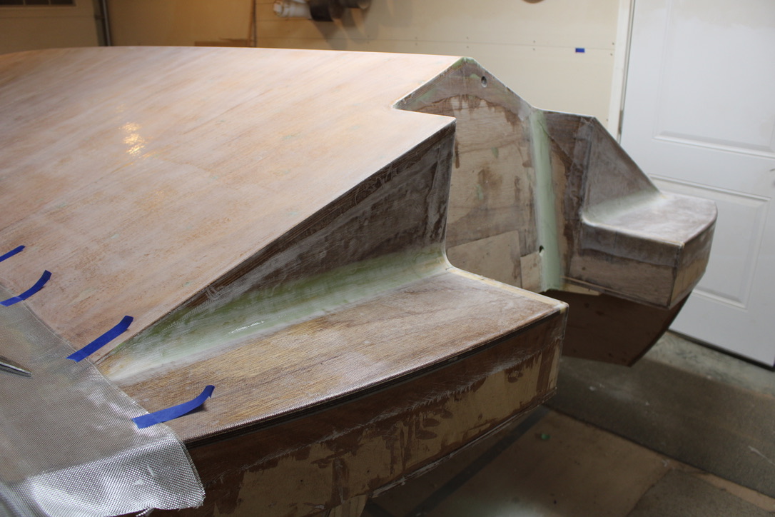
The photo below shows the hull bottom after placement of the glass fabric. The corners have been filled with a thickened two part epoxy filler that were sanded to shape. The back edge of the bottom surface was left as square as practical, for the most efficient water cutoff at planing speeds.

Experts disagree on two main methods of adding the glass fabric: laying out the fabric and then applying the epoxy or brushing a coat of epoxy on the wood first. Since the fabric catches on sharp or sticky things and deforms easily, I prefer to carefully lay it out over dry, sanded surfaces, primarily in one plane, as shown below.

A 36″ wide layer was rolled out and taped, overlapping the previous finished areas. With a smooth under surface, small changes can be made to smooth out wrinkles for the best possible fit.

The downside to this method is that the epoxy must penetrate the fabric, and fully bond to the wood underneath, or risk delamination later. The surface needs to be fully wetted and transparent, but not so much extra that would make epoxy flow zones. The application begins, rolling epoxy from top down, working out wrinkles as we go.

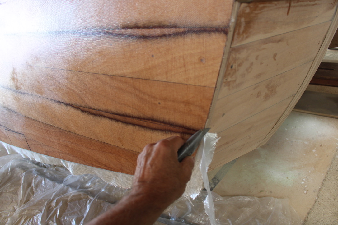
When the epoxy has set up to the stiff, not sticky stage, before it gets hard, the edges can be trimmed with a sharp knife.

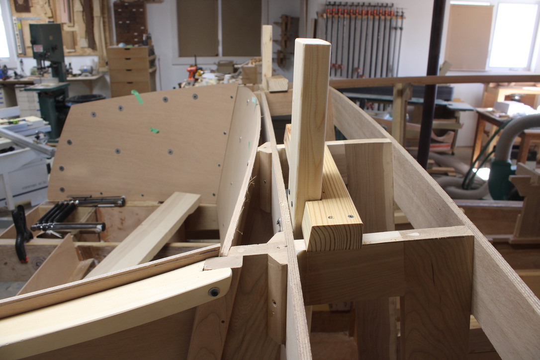
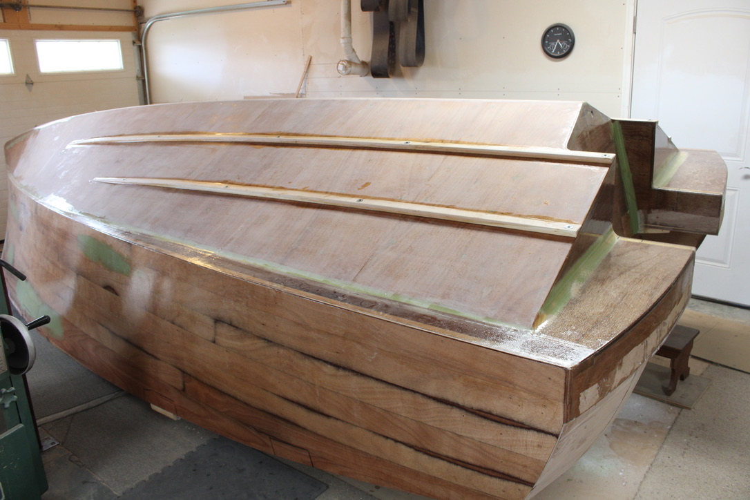
Next strakes were added, and rough sanding all over with 80 grit to allow best primer and paint adhesion. The hull planks of 4″ tongue and groove marine plywood show through on the sides. The dark lines show where the top ply layer was sanded through, and the green where low spots had been filled for final fairing.

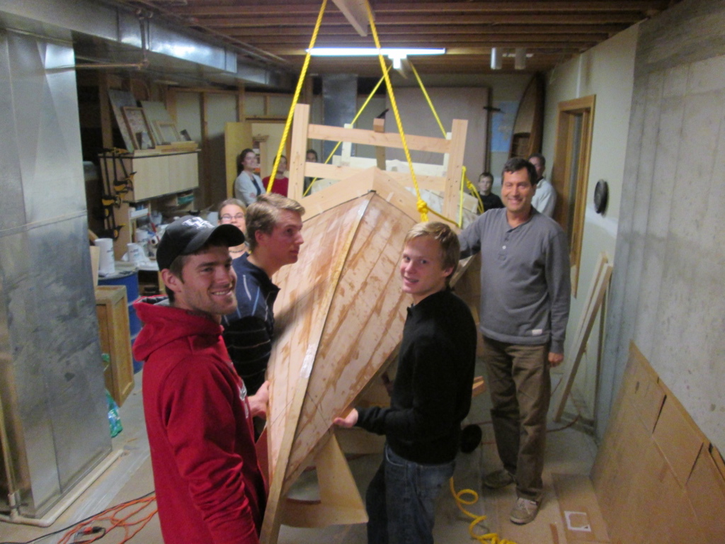
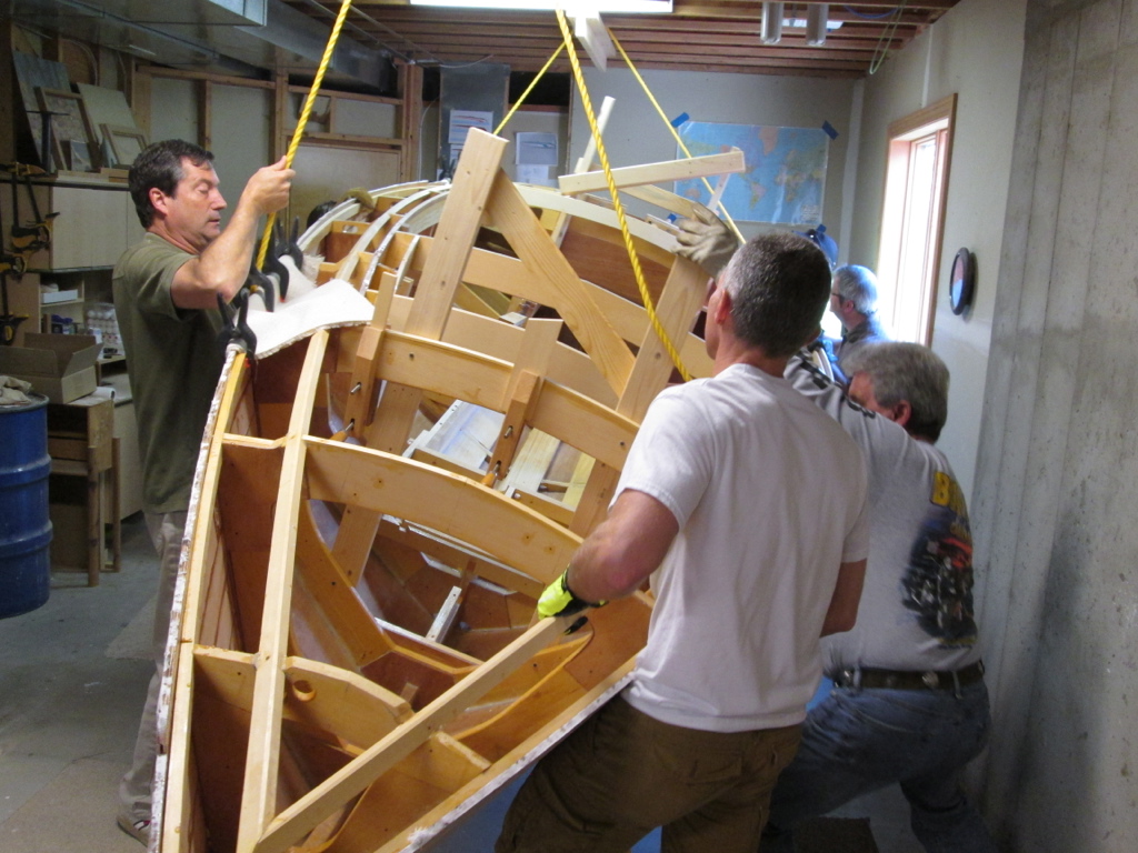
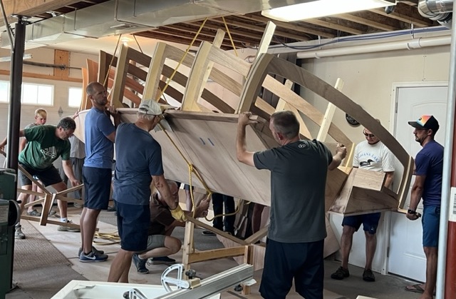
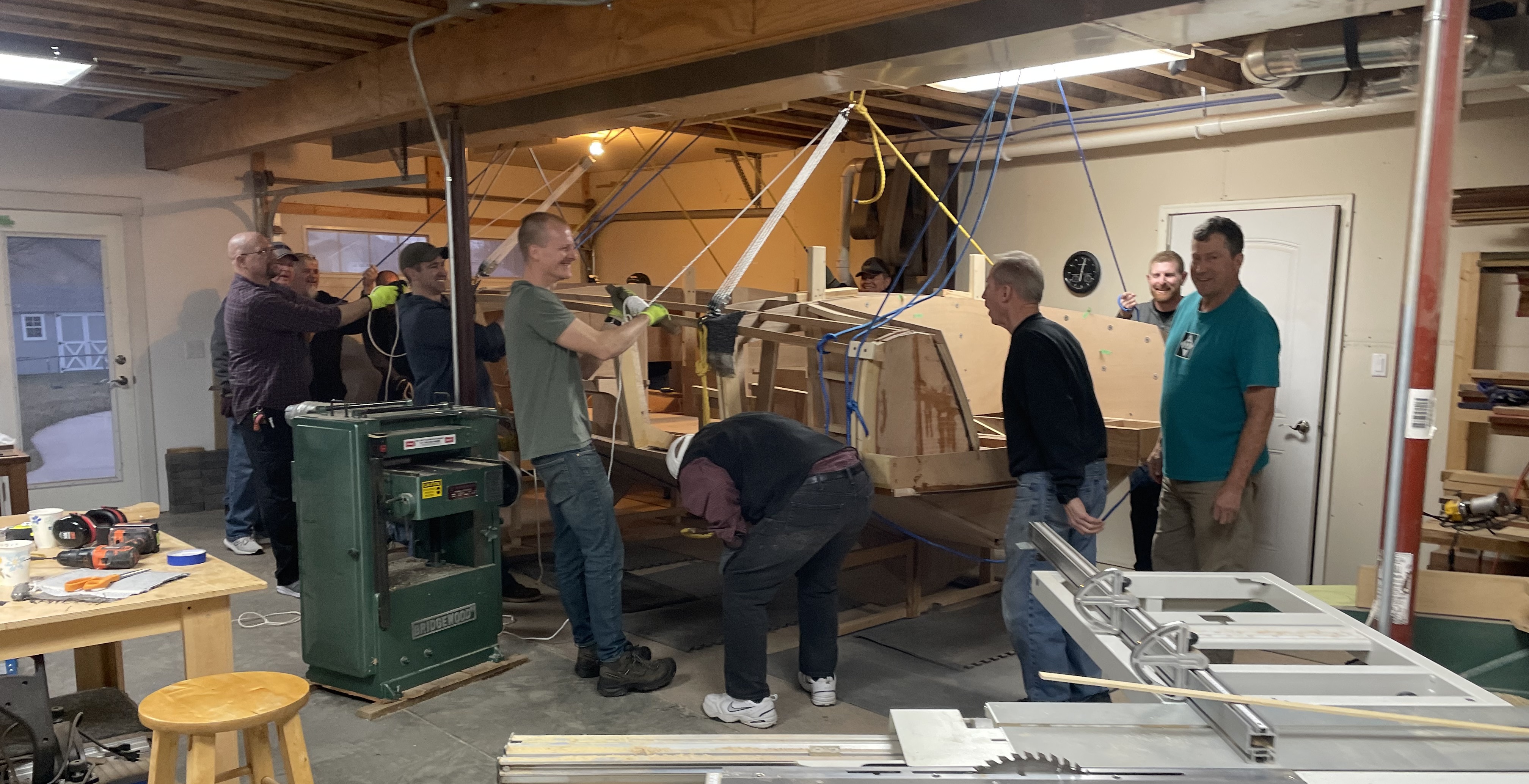
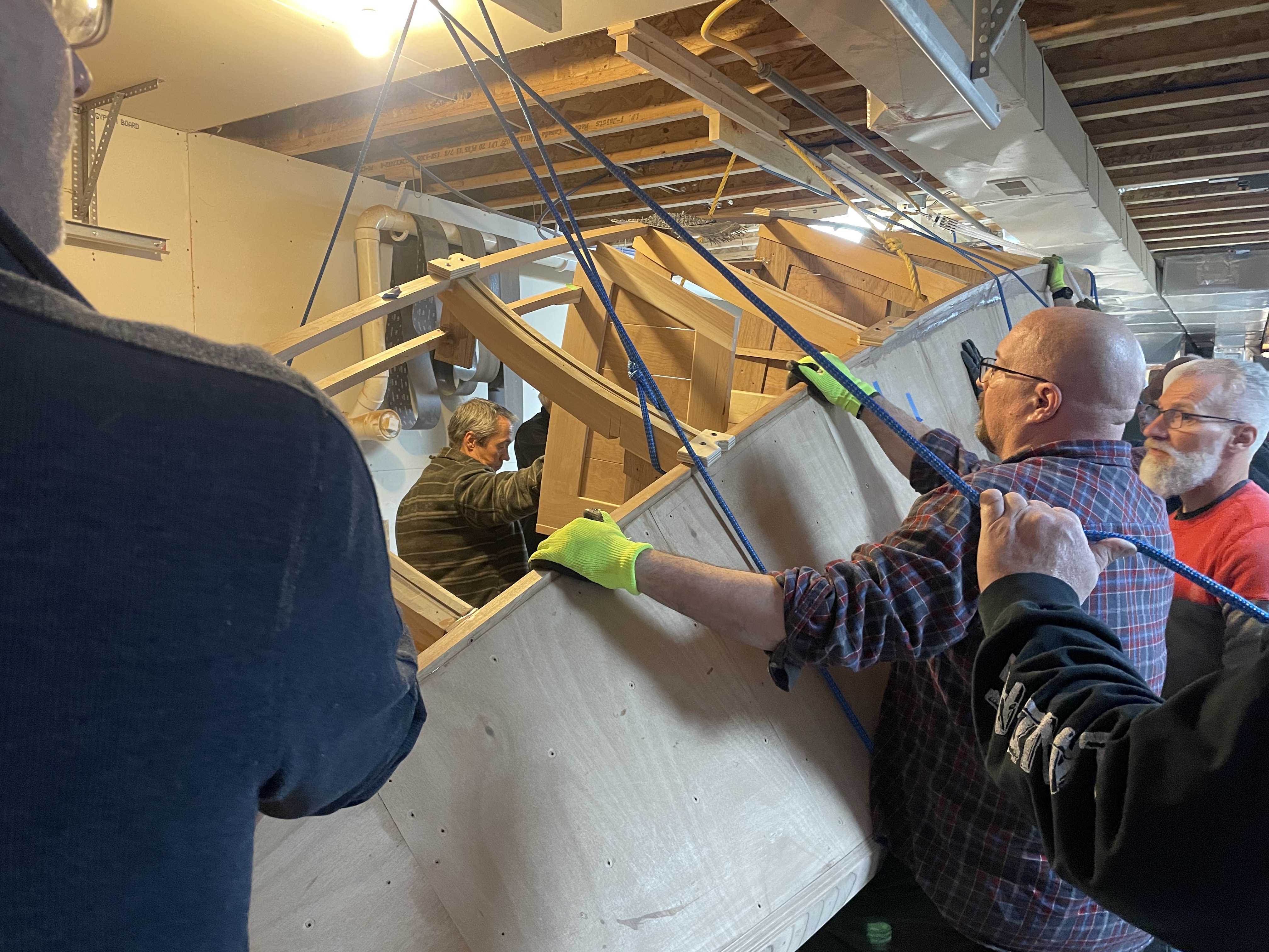
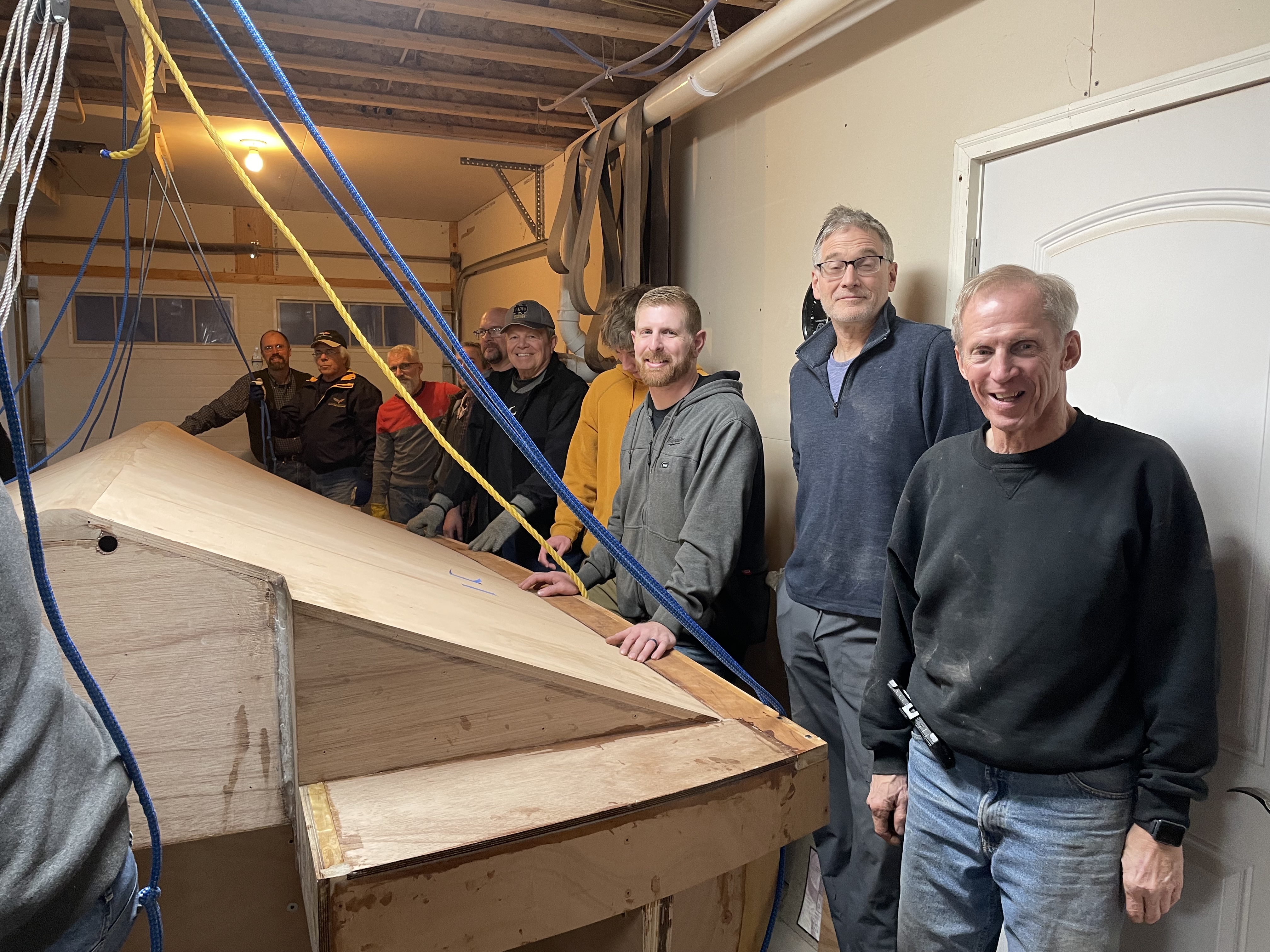
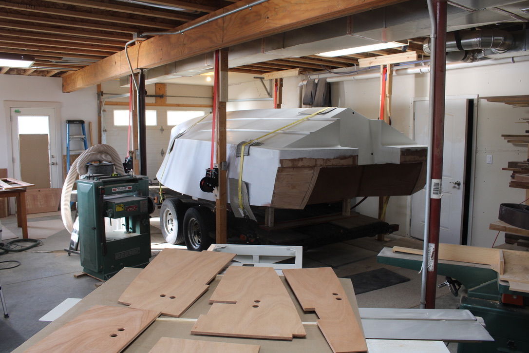
My shop is not equipped to spray paint , so the boat was loaded on a flat bed trailer and slowly hauled five miles to get professionally painted. This is on the return trip, preparing to lift the boat with the four heavy duty winches mounted on the temporary posts.

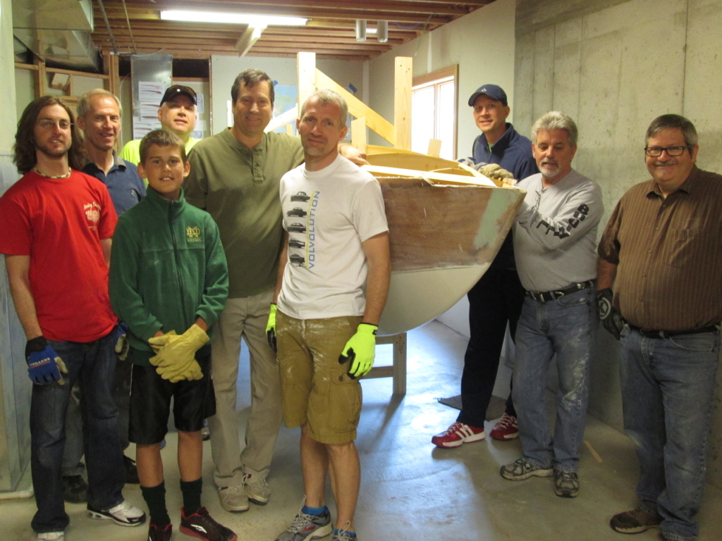
There are many ways to slow down a big project like building a boat, which happened but it is off and rolling again, passing this significant milestone. Work on the bottom is completed and following a final flip, this boat is intended never to be upside down again.

Crafting Beautiful Curves: The Art of Boat Design and Construction

All boats have some curved surfaces, and the most beautiful have many curves, all hopefully contributing to a cohesive complete package. Some modern boats have curves in only one plane, and that makes construction easier. But traditional wood boats, and ones I wanted to pay respect to, have surfaces with curves both ways. That makes hills or valleys and it gets complicated.

Below is the boat at completion of setting the long trim moldings that define the cockpit, and end at the stern. Now is the time to figure out the shape of the stern.

At the back on the outside, there is the inward curve or tumblehome, that adds width and buoyancy to the back, and just looks cool. And since an outboard motor on a wood boat can look out of place, the sides were extended to enclose it a bit.

New shapes usually begin in cardboard, then on to plywood if I need a rigid pattern. The piece of cardboard laying on top is to visualize how the wall of the engine well might look, and of course, it just came out curved as well.

That makes sense considering the back wall is also curved.

Then, to finish the double curve on the stern sides, internal runners were made for the first layer of tongue and groove shell to follow the side curve.

Eventually, it will be contoured, with both directions relating to both curves at the corner. The complication may be forgotten, and a complimentary form left standing. Beauty has a price.

Boat Turning Redefined

In the nearly five years of having a couple of boats in progress, the times to turn it over have occasionally gone smoothly, with a few scary moments. This was the first turn of the smaller boat when the framework was lightest. I just got some heavy duty nylon rope and attached some T-bar 2 x 4s to the rafters to hang it.

Light weight first boat turn

The next time had more oops and inefficiency spreading of the lifting power. The ropes did not behave as well as expected and a little floor bump occurred . . .

Heavier and more muscle needed.

But apparently all’s well that ends well.

Getting the boat out of the basement was a pretty tight challenge, but finally made it.

A couple of inches top and bottom.

And eventually it floated.

Les Chenoix Boat Show

The second boat, currently under construction is larger and made the first turn with a bit more muscle and finesse. We just about took out the light at one point.

Second boat, more weight and muscle, narrow miss.

The next turn got more complicated with a tangle of ropes that were difficult to adjust, and left a few guys holding the proverbial bag. This time we had trouble clearing the heat duct because the front pulley system failed and left it hanging down.

Front Pulley broken. . .

So, in the garden, look for help from someone with green thumbs. In the shop, look the guy in the green gloves, like Andrew Alger NEI above. NEI may not be a Purdue degree, but It stands for Natural Engineering Intelligence, and he has solved more than a few of our “make-something-work” crises.

Andrew came up with a new plan, as the boat needs a few more turns, and is getting heavier all the time. He suggested getting four reversible winches, to hang on support poles, with heavy duty nylon strap. I dutifully followed his plan and voila’ it became quite easy.

Two of us turned the winches to pull up on one side, and the other two released the strap to lower. A few adjustments of height and soon it was sitting right side up on the cradles.

All smiles for the success!

But for the two minute trip of the whole drama, check out the link below.

https://drive.google.com/file/d/1XqXfoPG8oKQIbxiQyNWPUzMbbIv_okh-/view?usp=drivesdk

Hull Planks and Contours

With the boat turned upside down the last time, the side planks need to be installed. They are made of 1/2″ marine plywood, cut into 4″ planks and routed with a tongue and groove to fit the best side by side. I alway start dry fitting a group, to see if the underlying cross frames are supporting fair curves.

In this case, I will not be doing the last few rows until the boat is flipped over and I can make sure the shape at the top line is good. But most of the side needed to be done in preparation for final painting of the bottom. Jeff Margush lends a hand, actually you could probably make the case that he might be doing the work mostly by himself.

After the epoxy dried, I needed to shape the plywood plank down to meet the longitudinal corner molding, called the chine. This Okume Marine plywood is the best plywood I have ever worked with, being almost as easily planed as solid wood. It is a woodworkers delight to have these wood curls roll up from a sharp blade in a good plane, especially the ribbons below.

After doing whatever wood removal is needed, then it was time to add some epoxy fairing compound to smooth gaps and add nice fillets to the corners. Between a rasp, a scraper, coarse sandpaper with flat or rounded blocks, and a dust brush, slow progress can be made. The proof will be in the pudding of a shiny paint job, to see if the contours are good.

A bit more fairing on the sides, finishing the bow and stern contours, and it will be ready for the next nerve racking step: putting a huge sheet of the glass fabric on and trying not to repeat the snafu that happened last time. Too much epoxy over a complicated surface ran and pooled in an ugly mess, that required many hours of scraping and sanding. This time I know what I am doing?

Building a boat seems like a continual learning project, and hoping not to have to repeat too many steps. Sounds like life . . .

Upside Down Again

A year ago, the cross frames of the boat were being set upside down, and the longitudinal parts like the keel, the chine and the sheer lines were added. Then the marine grade plywood was made into tongue and groove planks and installed on the hull bottom. 

When that was finished, it got flipped up right so I could work through the sides to build more floor support, the transom and seat framework. Just recently, that construction got pretty close to done, so it was time to turn it again.  The boat is heavier than the last time we rotated it, and with less parts to grab, I thought more ropes might help. . .

Hanging From the Ropes

Below, you can see Steve Rimes and Andrew Alger on the two pulley systems, with Don Florea, doing the quality control inspection. There are Dustin Friend and Kenyon Lederman holding ropes while Dave Ziegler, with the white hat, inspects the clearance to remove the cradle. Not sure how much I am not helping.

Steve supplies the lift on the 8:1 pulley system, while Todd Lederman, Kenyon and all the rest, help start the rotation.

Starting Rotation

On the front end, Jeff Margush has just pulled out the cradle that the boat had been sitting on before. Andrew Alger handles the pulley ropes, with another dozen guys manning their stations.

Busted Rope

It was all good until the rope connection at the ceiling for the front pulley gave way. The T-shaped 2 x 4’s screwed to the ceiling joists held firm, so the rest of the ropes were still useful. It just took a bit more muscle. Below are Don Florea, Chris Friend, Mike Friend, David Veale, Doug Martin, Kenyon Lederman and others.

Ceiling Clearance?

It was too late to turn back, and with the many ropes holding up or giving slow braking, we are half way there. At this particular moment, the left side needed to go down a bit for the right to clear the heat register. It had worked out with a tape measure and on paper!

Andrew Alger and Jeff Margush are getting it figured out.

As one guy said, “This is a pretty small shop for a boat this big!” We were always looking out to keep it off the floor and still miss the heat vent and the light fixture. In this case we had to scoot it left and restart the rotation. 

Halfway there

David Veale, Doug Martin, Jeff Margush, Andrew Alger and and Dave Ziegler lift and turn.

Eventually, the boat came to a soft landing, and the ropes were released from their loads. The new base was intentionally positioned low enough to easily work all of the way across the bottom. This last upside down phase will be for final fairing, adding glass fabric embedded in epoxy, adding primer, fine sanding and final paint. 

Sounds simple enough. The paint expert, Dustin Friend, is third from right and has an “I wonder” smile on his face. There might be some trouble shooting required. Dustin, Chris Mike black hat

Thanks to Don Florea, Todd Penner, Dustin Friend, Josiah Penner, Chris Friend, Andrew Alger, _______, Jeff Margush, Mike Friend, David Veale above.

Thanks also to Bob Friend (behind me), Todd Lederman, Steve Rimes, Kenyon Lederman, Dave Ziegler (White hat), and Doug Martin, below.

Under the Surface

Before the hull planks go down and create the beautiful curve shapes, the interior frame work has to be ready for the hard work. The boat must be built strong enough to be lifted by three points, one in front and two from each side of the stern. It would be a grand shame to see the boat chained and raised off the temporary trailer, and watch it drop from a failing U-bolt. 

The same area in the back will also needs strength to hold a ski/tube rope, and tie downs to the trailer when traveling.

The top of the back cross frame has been cut off to make room for the motor well, but the remaining C-shape sides are the most obvious place to begin building strength.  

More plywood layers were added on the inside and out, connecting the top and bottom to make a strong outer panel. They are bonded with epoxy which is very tough and does a better job of filling gaps than most other glues. 

If I had planned perfectly, the outer longitudinal beam would have been right up against the glued layers. But instead, the deck needed more space for the folding ladder, so I had to add some filler layers.

To fill the gap, I epoxied the marine plywood blocks to the long beam. The speckled markings are shallow holes drilled to allow the epoxy to grip a deeper layer, and resist a shear sliding force.

Next, another plywood panel was constructed beside the longitudinal beams. It is beginning to show the 3D shape of the stern extensions.

This is the group of eight plywood pieces that went into making the left (port) side wall. The right side was about the same. It did get a little complicated. The morning that I planned to glue both sides turned into a whole afternoon and made me late for supper.

Since the middle wall was slanted out, in the way that looked best to me, I had to make some perfectly angled wedges to glue in the gap.

They were made from a Douglas Fir 2 x 6. By angling the cross cut fence and flipping the board over each time, eventually I found an angle that worked great. 

Since the wedges were cross grain, when I applied the epoxy, it soaked in to the large pores and (I believe) became a very strong wood and epoxy link. 

If this was a production boat, I suppose some testing would be in order to see if my seat-of-the-pants engineering worked out. Especially since the last time I took the 2016 wood boat to the dealer for motor service, they told me that the transom was cracking.

Now this was a surprise, because it has always been a concern. I do inspect on occasion to see if that last big wave or the bumpy railroad tracks, may have crossed the limit of the transom’s strength. So, I asked the mechanic to show me the problem area, and he pointed out some cracks on the back stern panels , not really a part of the motor mount area. 

It is annoying but fortunately not serious, as the issue is sun damage. The mahogany veneer is developing small cracks because it was less protected under the boat lift canopy. So, with no major engineering failure on the previous boat, I take it as my cue to carry on. Inspectors Jeff Margush, Don Florea, and Andrew Alger will be relied upon to set me straight.

The stub cross frame now has five half inch marine plywood layers, and the longitudinal panel has three layers.

Slowly, slowly, the work on the inside frame is getting done. It gets tedious, and without glamour, to put some pieces in place that soon will never be seen again. But when the big waves and bumpy road comes to stress the pretty boat shell, what’s inside gets much more important and obvious. It is like a life well built. 

Inner Trim Line

The outside deck line is created with the 1″ x 1.5″ long molding called the sheer line. The next step is creating the inner trim line which defines the deck and the seating space. The blue tape seen below left is first visual experiment.

For the molding, I picked a 12 ft. piece of straight grain cherry. Granted, it is not the world’s first pick for boat building wood, but it is available, of medium density, and works superbly. I also had plenty on my wood rack so I decided to “shop local.”

To make a 22 ft. continuous molding, I had to splice two pieces with a 20 inch long scarf joint. It goes the full distance of the paper below. By making it long, it allows basically the same bending characteristics as the other solid pieces.

The left side is shown with the long molding ready to install. The nails and string show the refinement of the line, and allows a visual inspection to see if it follows a regular or “fair” curve.

It passed muster and served to position the cutout notches. They were cut with a hand saw, chisel and rasp, as needed to seat the molding the right height and along the curve.

The most difficult notch was the front, which did not go all the way through. I cut as far as possible with the Japanese pull stroke handsaw (bought at Menards).

Necessity is the mother of invention, so I figured the drill might do as well as hammering with a chisel on the white oak front frame.

Then a bit of the easier vertical chopping to take out waste.

And the half mortise was ready to final fit.

After the curve of the entire runner was micro adjusted to suit the eye, it was bent into the notches and bonded with epoxy. It becomes a visual line and a strength element, and the structural organizer for all of the interior spaces.

The umteenth step of the impossible journey is done but a seemingly endless list awaits. Tomorrow . . .

Curves and Corners

From the beginning of building a boat, a grand attempt is made to follow plans, if you have some which I do not, and keep both sides symmetrical. That applies especially to the level, straight and and flat parts.

But the most visible and beautiful lines on a boat are at the edges, on the side, and the transom end. Those are mostly curves that are not so easy to measure, so the eye makes the final judgement on whether a line looks fair and pleasing.

This time it was figuring out the outer, lower curve of the transom. As usual, it starts with a pencil on paper. Then, I often use a thin bendable stick, shown at the bottom, to visualize the full size 3D shape.. Below, the bottom pieces complete the line, and compliment the top deck edge molding (sheer line), in smooth symmetrical curves.

Here is the side view of the full size cardboard and 1/4″ plywood patterns in preparation for the curved back corner lines.

Admittedly, the wooden boat building world is small, but when I hear of another builder, I like to meet and discuss construction ideas with them. So, it was my pleasure recently to be introduced to Charles Onyon, who has an interesting resume’ including working four years at Van Dam Custom Boats. A few years ago, I visited and took a tour of their inspiring shop, likely the premier boat building company in the country.

Charles came over to visit, and gave a far more educated scrutiny of the boat than the average house guest. He knows boat building including wood types, joinery, paint selection, and engineering for strength and esthetics. He is smiling because most people don’t know he is a celebrity . . .

3D Boat Shape

The end of the story from the last post is shown below, as I am tuning up the final angle where the sheer log meets the bow. It may look simple enough, but hanging on to a screaming body grinder at a precise angle with 36 grit paper is no casual task. I could have used a saw and a file, but, if the edge is visible and there is room to move, it is the fastest and most direct path toward completion.

I have long wondered what built by hand means, but if it is anything beyond shaping something strictly with your fingers, then this concentrated, practiced effort has to qualify also. Taming the body grinder is on par with training our Boxer dog Buck.

He never was fond of the leash, and pulled continually toward the next interesting scent or dead treasure. We always had to be prepared for the surprising and potentially injurious jerk, should any rabbit or any other animal jump to flee.

The grinder can be a lot like that dog. It pulls, it whines, it catches and jerks, all the time requiring it be handled with gentle pressure. But if it is mastered, it pulls as hard and fast as an Iditarod sled dog.

Those long sheer logs or moldings are now faired, and assembled into the framework of the boat. Now, it allows the imagination to go down the road a ways, as the 3D shape is coming into view.

Sheer Magic

The line where the top of the boat meets the side is called the sheer line by traditional builders. It is never straight, and is a defining shape of the personality of the boat. Sometimes it starts high in front, to cut the big waves, and comes down in the middle perhaps for rowing or fishing. This beautiful rowboat shows that reverse sheer.

My speedboat on the other hand, will not be battling such severe weather, but will need great visibility forward at all times. In this case, it has a positive sheer line, lower at the front to see across, and higher in the cockpit area for seating comfort and wind protection.

The line always curves inward toward the front, and the whole shape must be “fair,” a beautiful shape. Fairing a curve means making the shape flow with out hills or valleys. Lumpy does not make a winner. The best help for a good curve is a slender board long enough to go the full distance, thin enough to make a consistent bend, and thick enough to resist distortion between supports.

I chose a piece of cherry, and sized it to 7/8″ x 1-1/2″, and then had to splice together 2 twelve foot pieces to make 20 ft. As noted in the last post, the first one broke under the pressure of bending. I picked a straighter grained piece, thinned it a little, and started over. Below is the scarf joint, angled over 14″ so when glued, it will behave mostly like a solid original piece.

Then, the process begins by cutting a notch at the corner of one cross frame, and gradually fitting the sheer log in place. The photo below shows starting in the middle, using a bungee cord to hold it and then going on the next frame. Not a step to rush, as it will be examined, praised and criticized ad infinitum should this boat ever get on the water.

My friend Stan Oyer asked if there is a point in boat building when you have to give up the tight tolerances of levels, angle guides, and tape measures. Yep, and this is another of those many times. Below, I spring clamped two straight sticks to the extended sheer molding, just to see if the angle is similar side to side. I did not measure, or level up, but just got back and looked at the two sides from a couple of angles. My conclusion is that they are beautifully compatible, if not perfect.

On to the seat framework coming up . . . You are never lost until you are out of time.