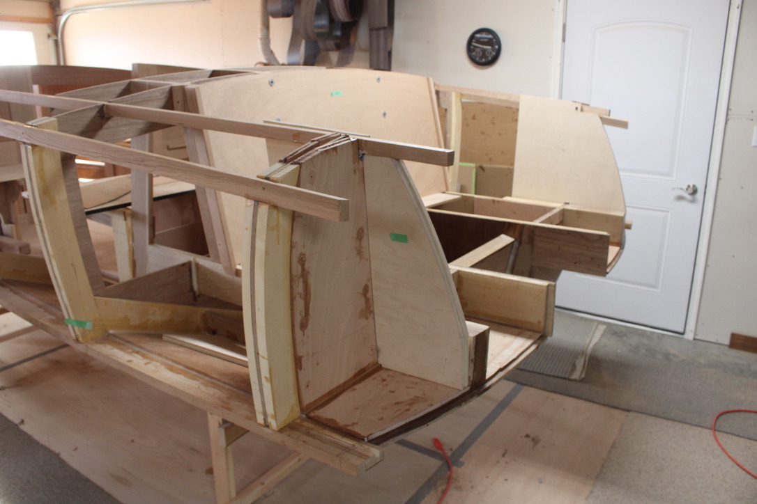
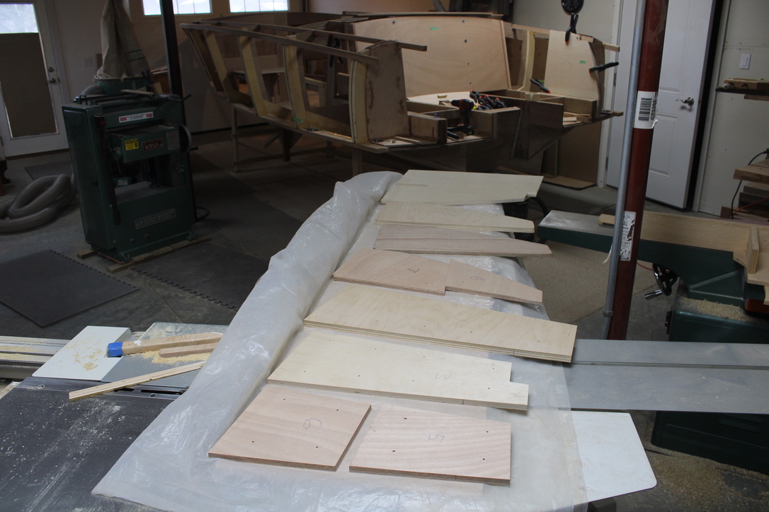
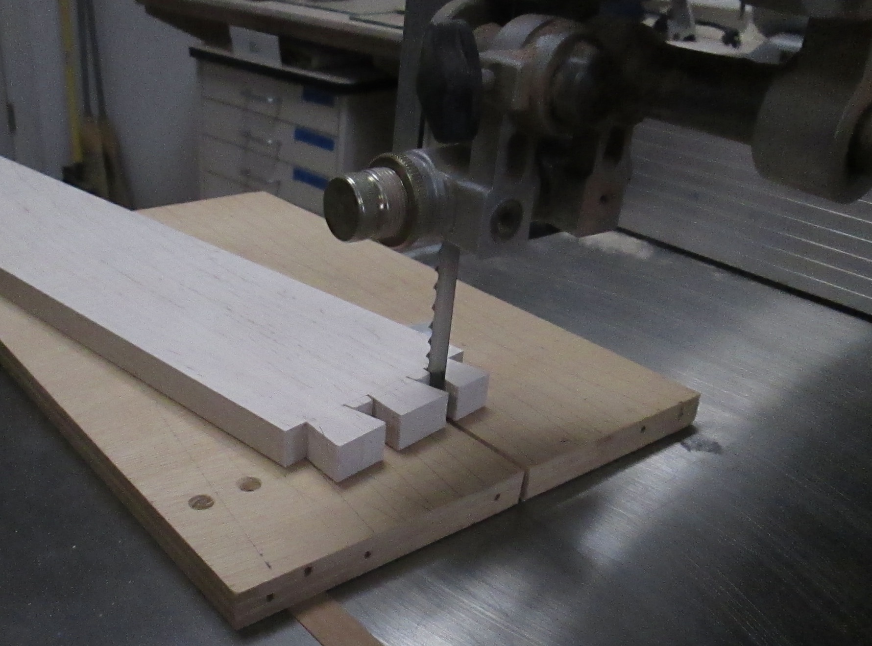
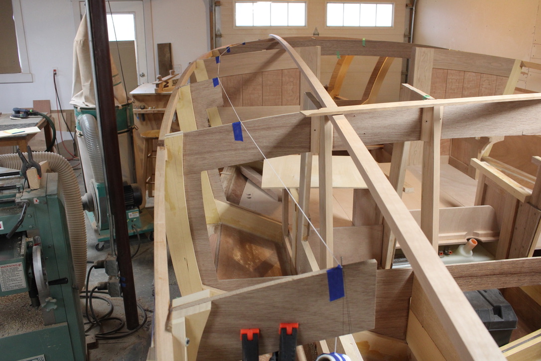
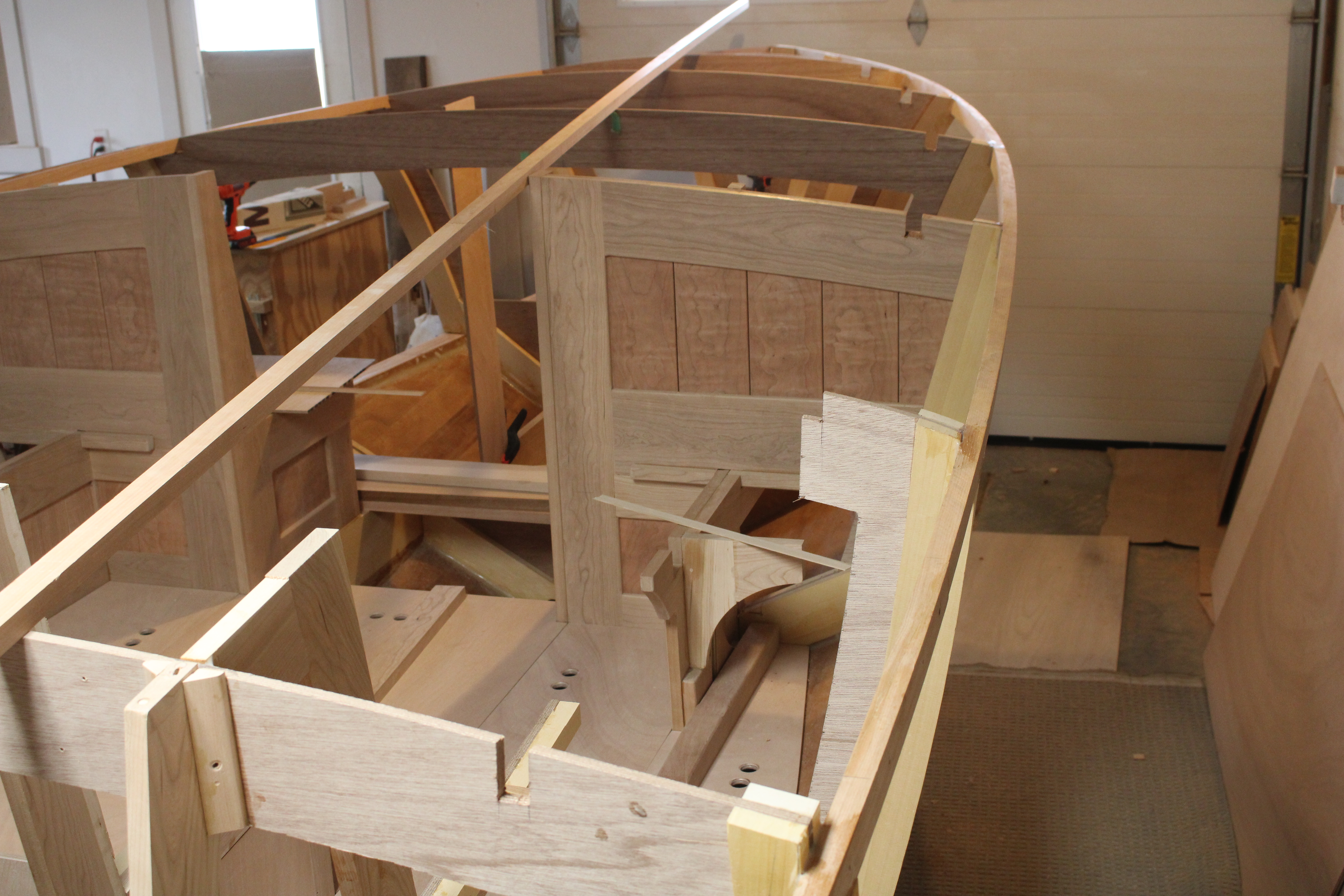
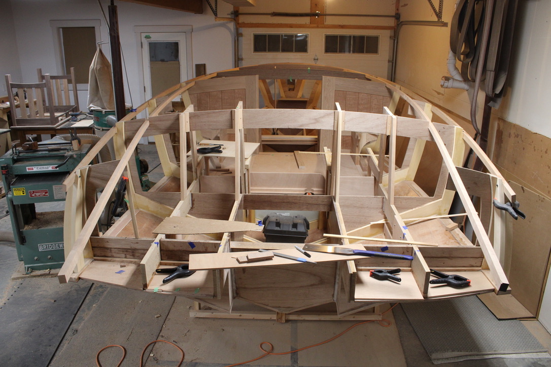
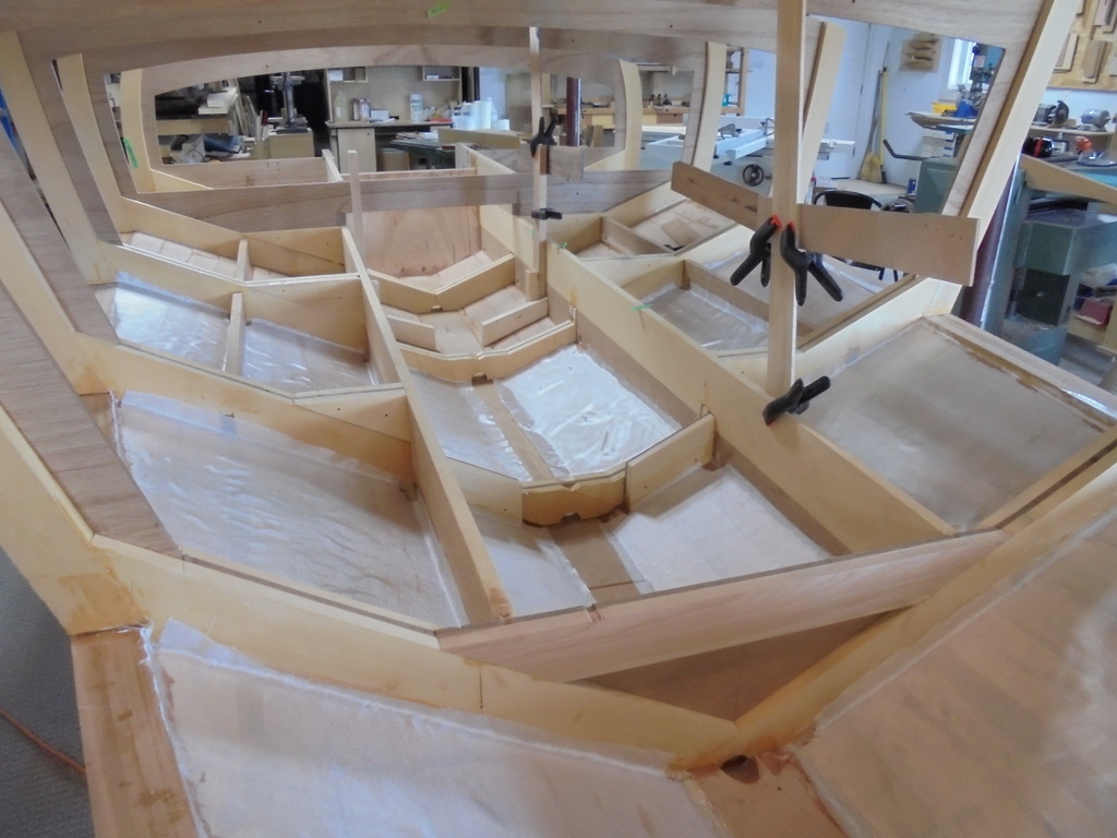
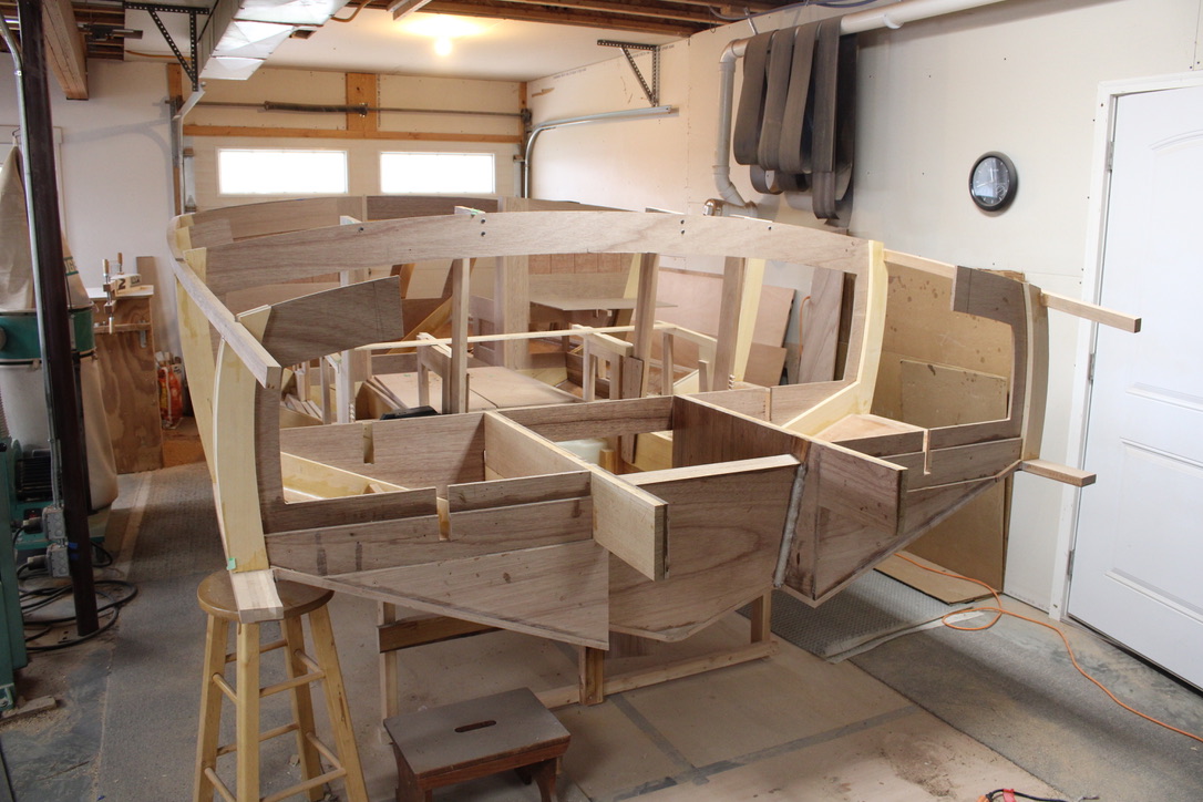
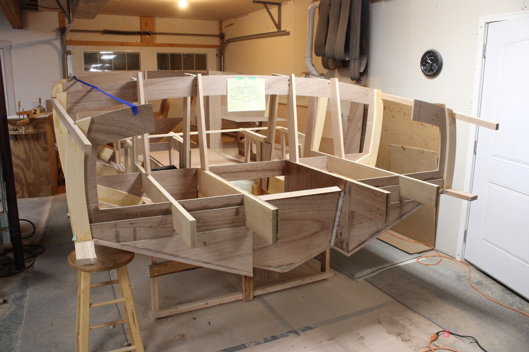
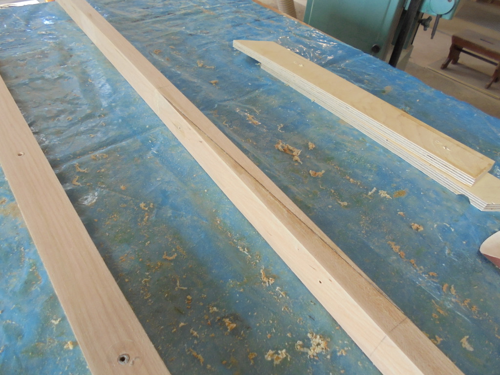
A year ago, the cross frames of the boat were being set upside down, and the longitudinal parts like the keel, the chine and the sheer lines were added. Then the marine grade plywood was made into tongue and groove planks and installed on the hull bottom.
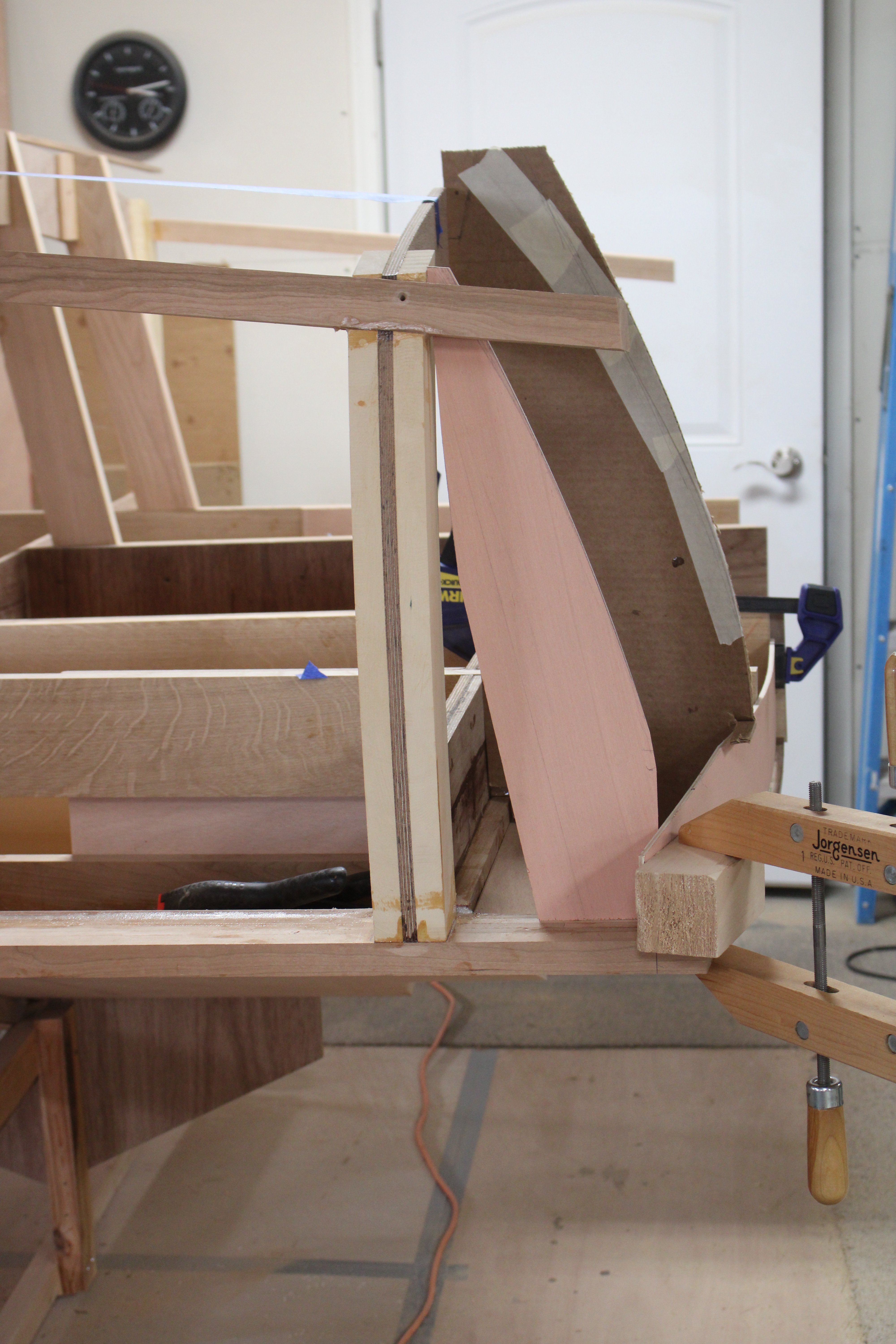
When that was finished, it got flipped up right so I could work through the sides to build more floor support, the transom and seat framework. Just recently, that construction got pretty close to done, so it was time to turn it again. The boat is heavier than the last time we rotated it, and with less parts to grab, I thought more ropes might help. . .
Hanging From the Ropes
Below, you can see Steve Rimes and Andrew Alger on the two pulley systems, with Don Florea, doing the quality control inspection. There are Dustin Friend and Kenyon Lederman holding ropes while Dave Ziegler, with the white hat, inspects the clearance to remove the cradle. Not sure how much I am not helping.
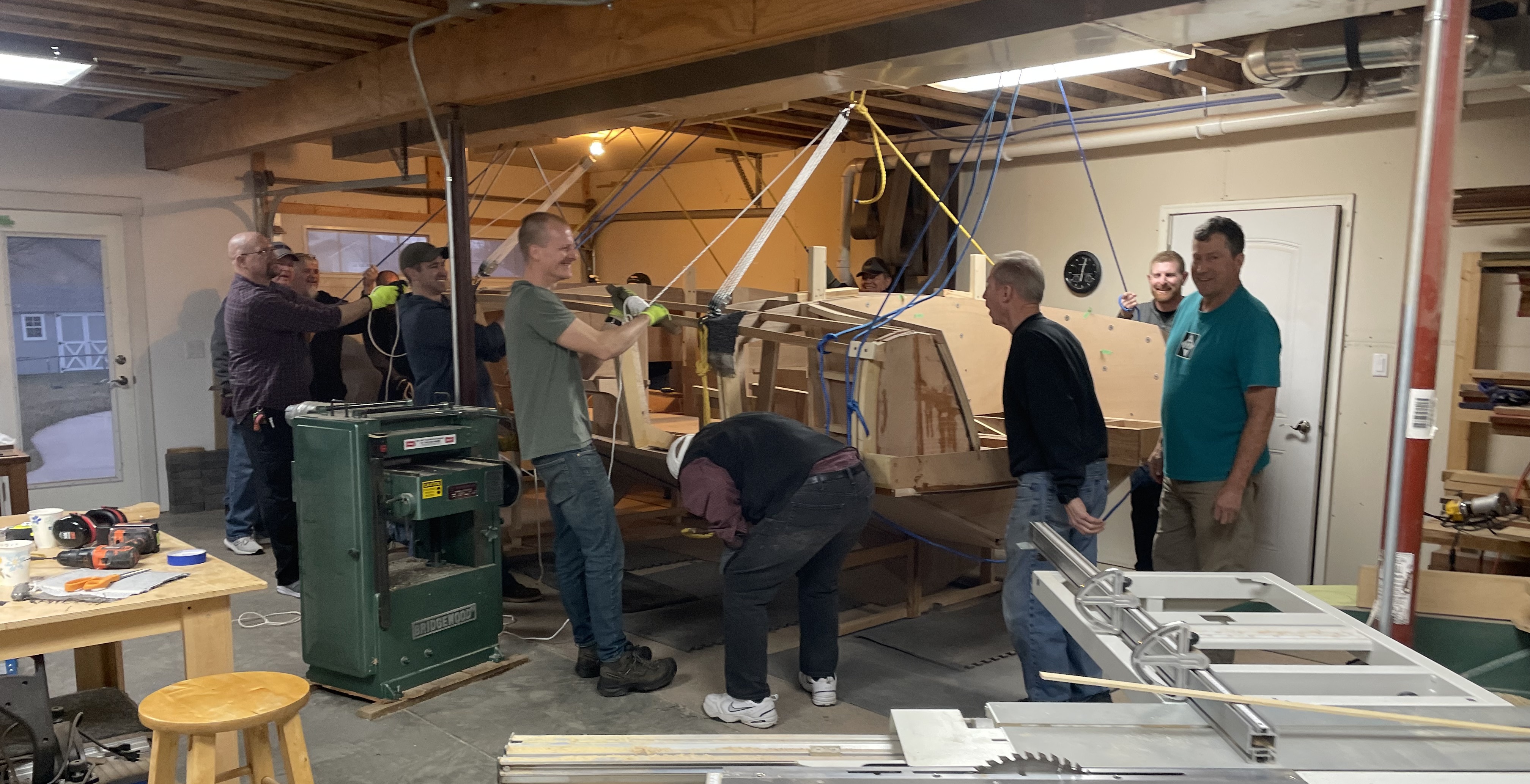
Steve supplies the lift on the 8:1 pulley system, while Todd Lederman, Kenyon and all the rest, help start the rotation.

Starting Rotation
On the front end, Jeff Margush has just pulled out the cradle that the boat had been sitting on before. Andrew Alger handles the pulley ropes, with another dozen guys manning their stations.

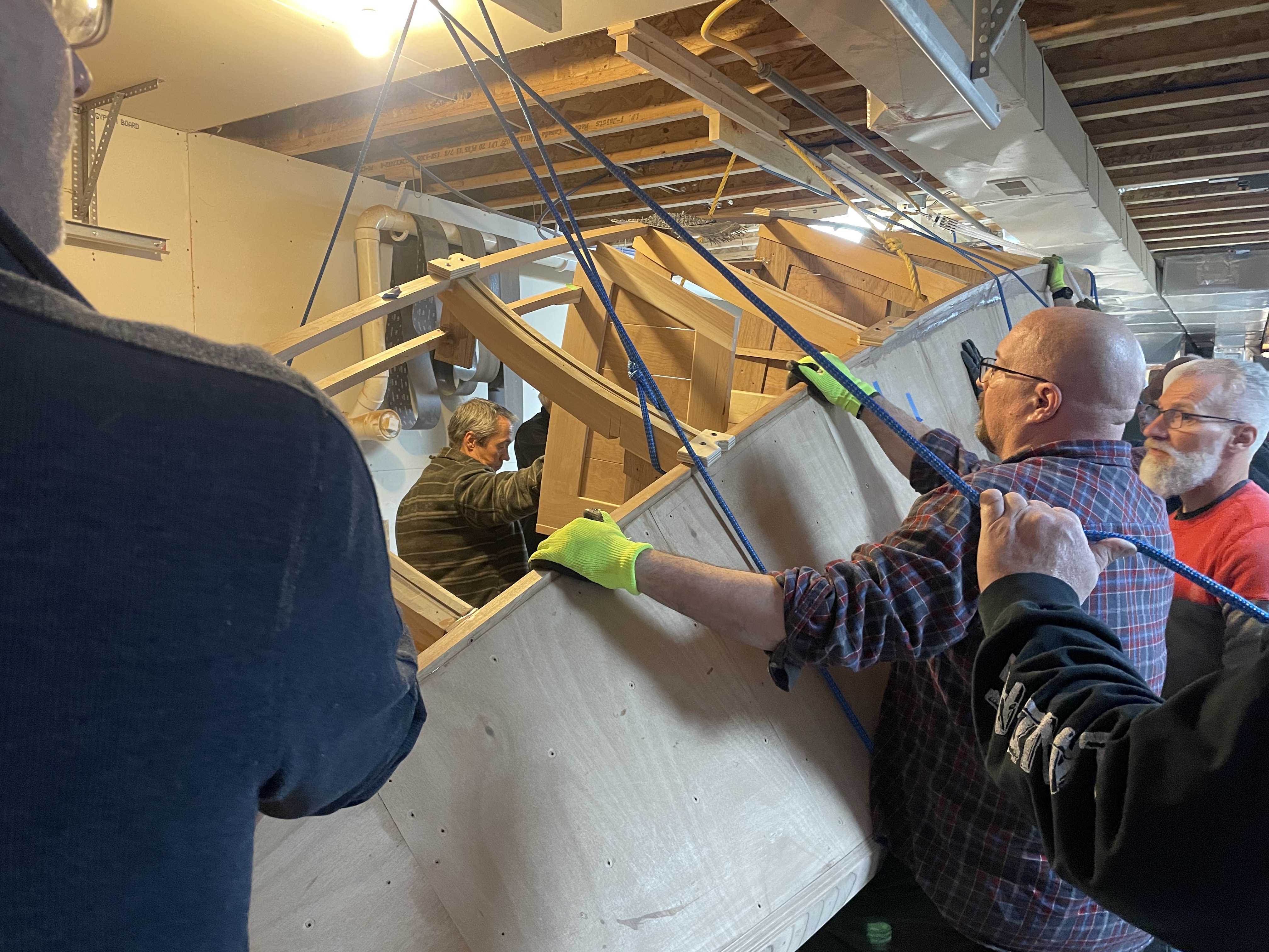
Busted Rope
It was all good until the rope connection at the ceiling for the front pulley gave way. The T-shaped 2 x 4’s screwed to the ceiling joists held firm, so the rest of the ropes were still useful. It just took a bit more muscle. Below are Don Florea, Chris Friend, Mike Friend, David Veale, Doug Martin, Kenyon Lederman and others.

Ceiling Clearance?
It was too late to turn back, and with the many ropes holding up or giving slow braking, we are half way there. At this particular moment, the left side needed to go down a bit for the right to clear the heat register. It had worked out with a tape measure and on paper!
Andrew Alger and Jeff Margush are getting it figured out.
As one guy said, “This is a pretty small shop for a boat this big!” We were always looking out to keep it off the floor and still miss the heat vent and the light fixture. In this case we had to scoot it left and restart the rotation.

Halfway there
David Veale, Doug Martin, Jeff Margush, Andrew Alger and and Dave Ziegler lift and turn.

Eventually, the boat came to a soft landing, and the ropes were released from their loads. The new base was intentionally positioned low enough to easily work all of the way across the bottom. This last upside down phase will be for final fairing, adding glass fabric embedded in epoxy, adding primer, fine sanding and final paint.
Sounds simple enough. The paint expert, Dustin Friend, is third from right and has an “I wonder” smile on his face. There might be some trouble shooting required. Dustin, Chris Mike black hat
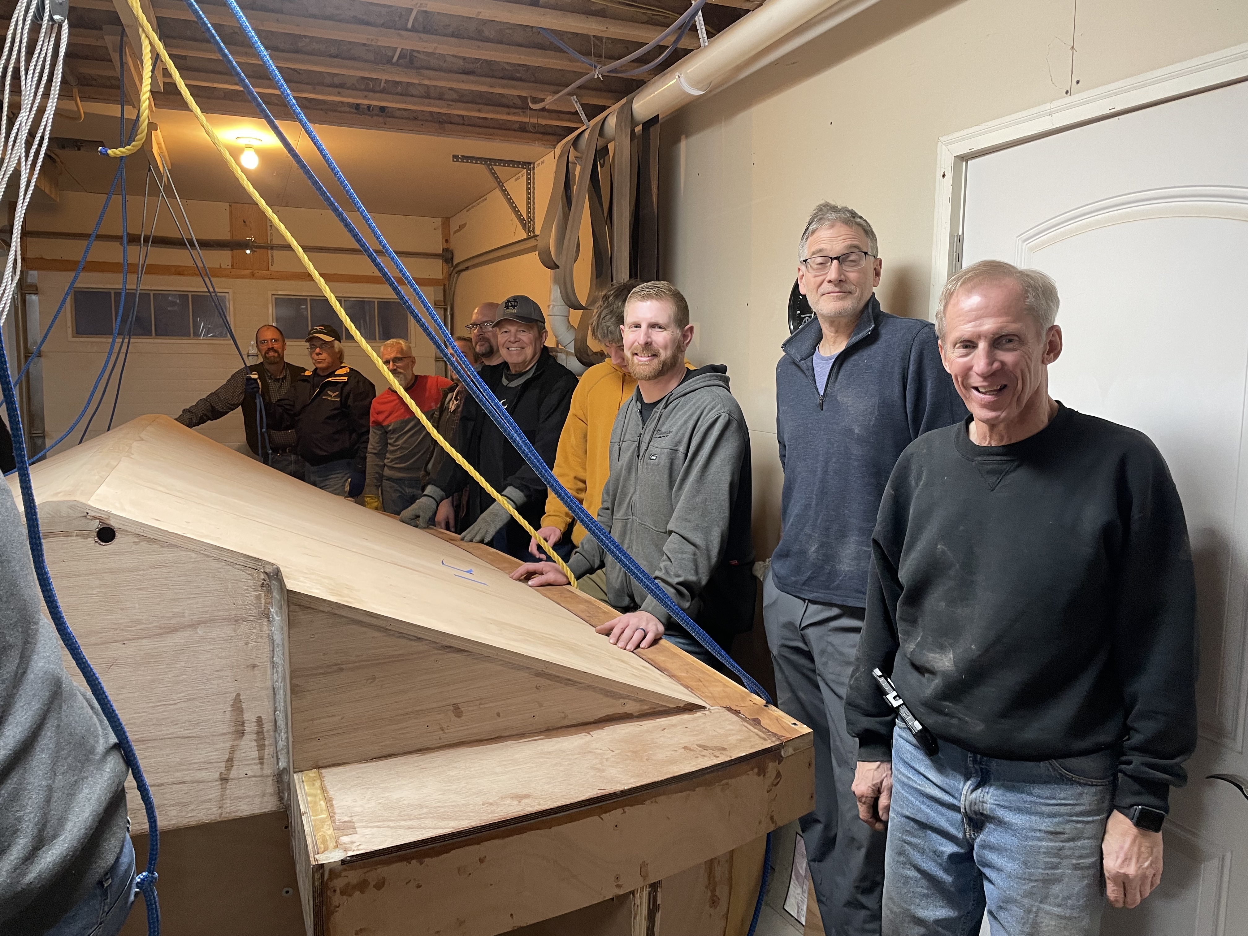
Thanks to Don Florea, Todd Penner, Dustin Friend, Josiah Penner, Chris Friend, Andrew Alger, _______, Jeff Margush, Mike Friend, David Veale above.
Thanks also to Bob Friend (behind me), Todd Lederman, Steve Rimes, Kenyon Lederman, Dave Ziegler (White hat), and Doug Martin, below.