Good Bye to the Strongback

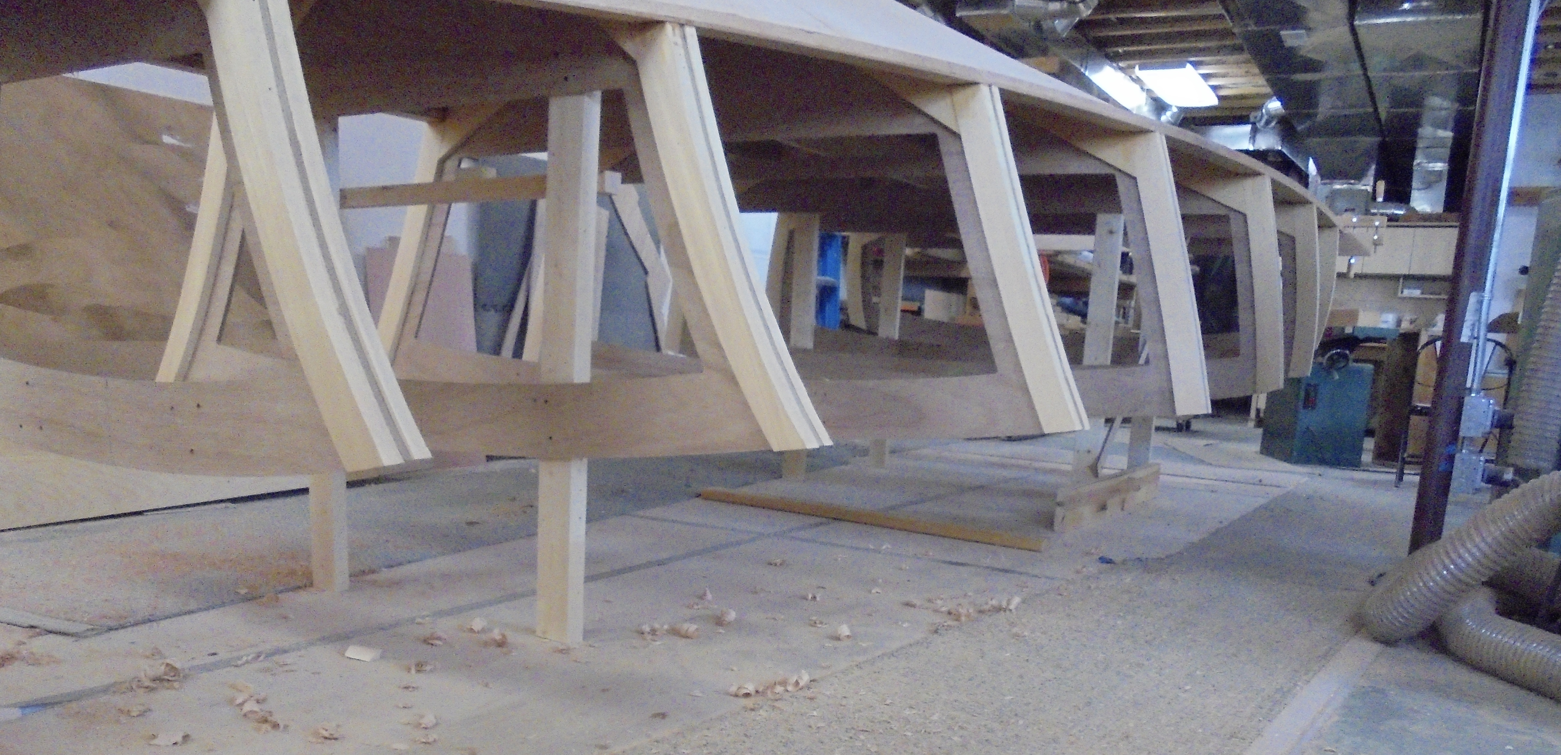
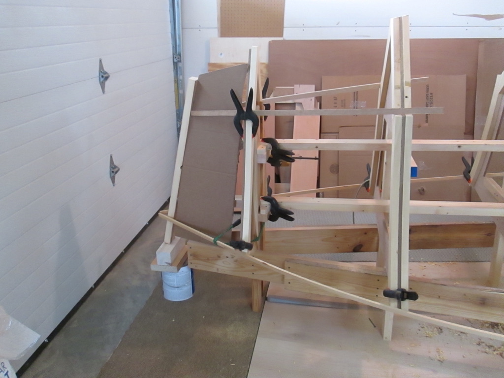
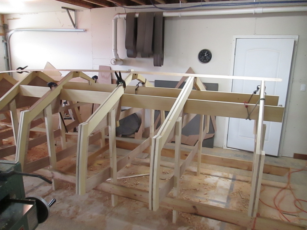
Sooner or later, the endless list of final things to do comes to an end, or at least to the beginning of a new stage. A lot water has gone over the dam since the beginning of this boat started about 7 months ago. The strong back is the under assembly of horizontal 2 x 6’s and vertical legs that was built to hold the cross frames in the right position.

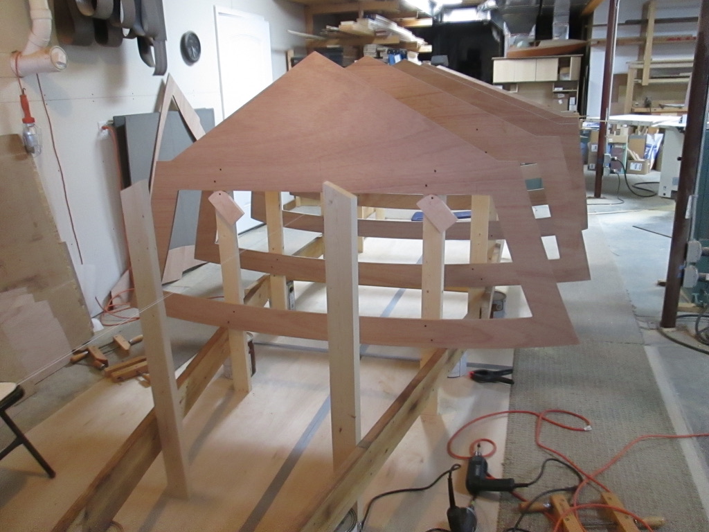
Gradually, longitudinal beams were added to connect and strengthen the frames.

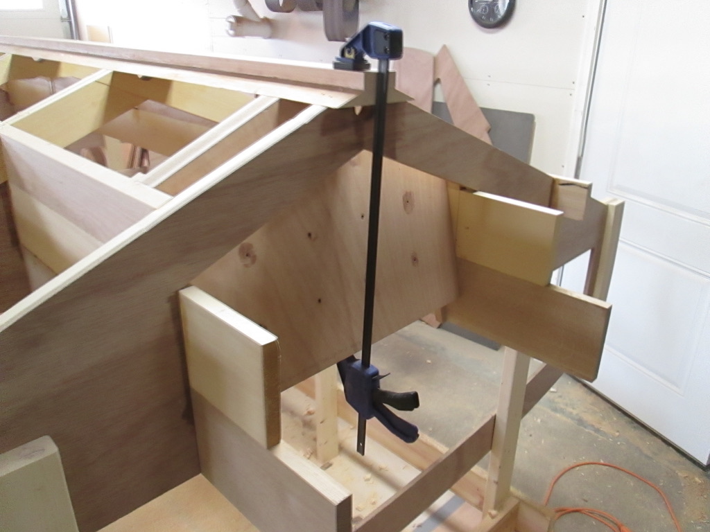
The keel was added and the transom was mounted inside the support beams.

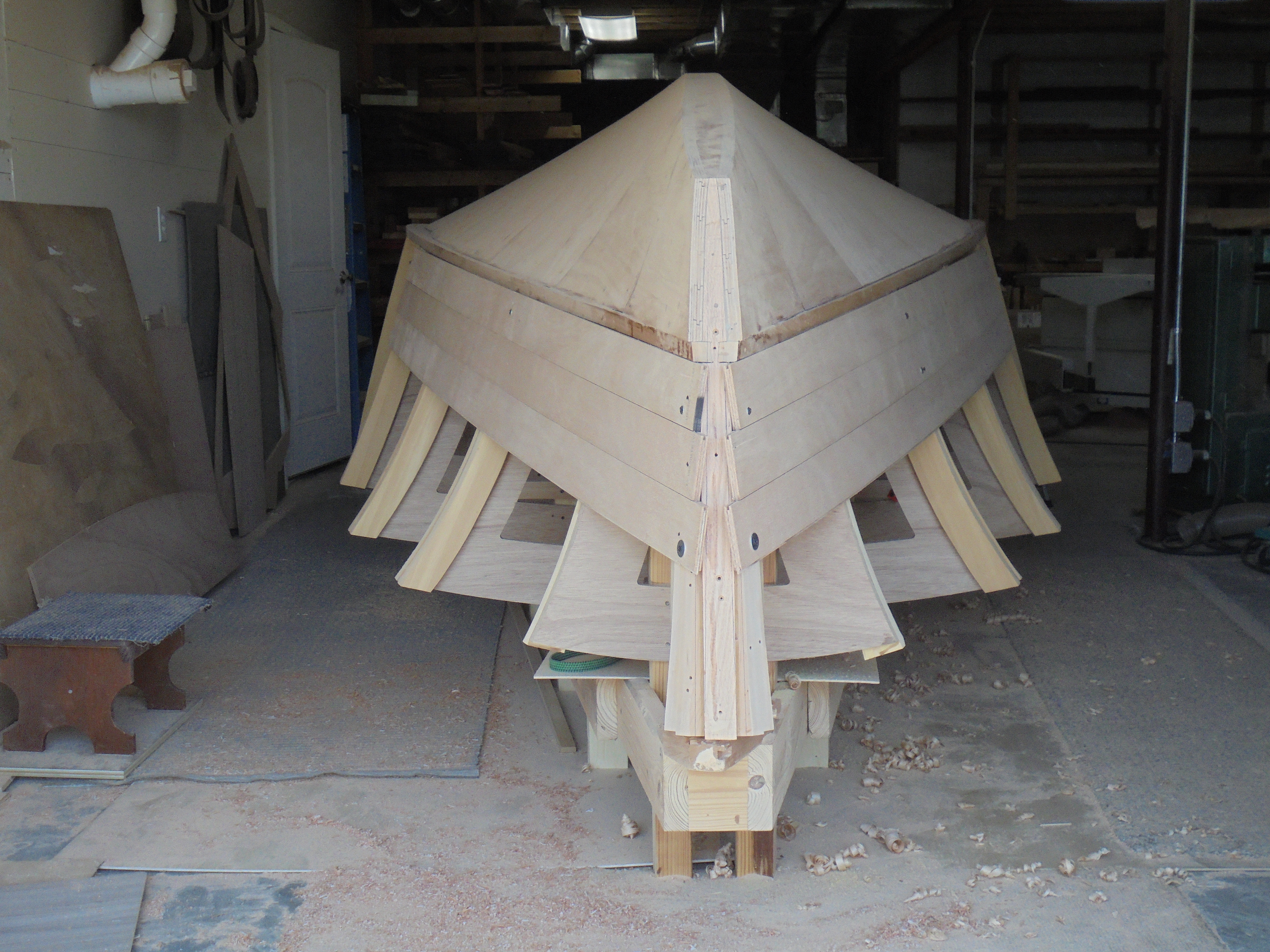
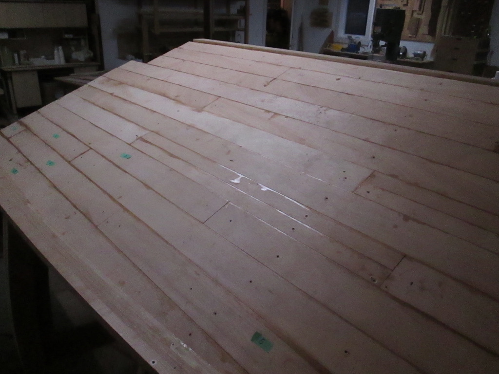
The hull planks and the chine runner were installed.

The second hull layer was added and faired.

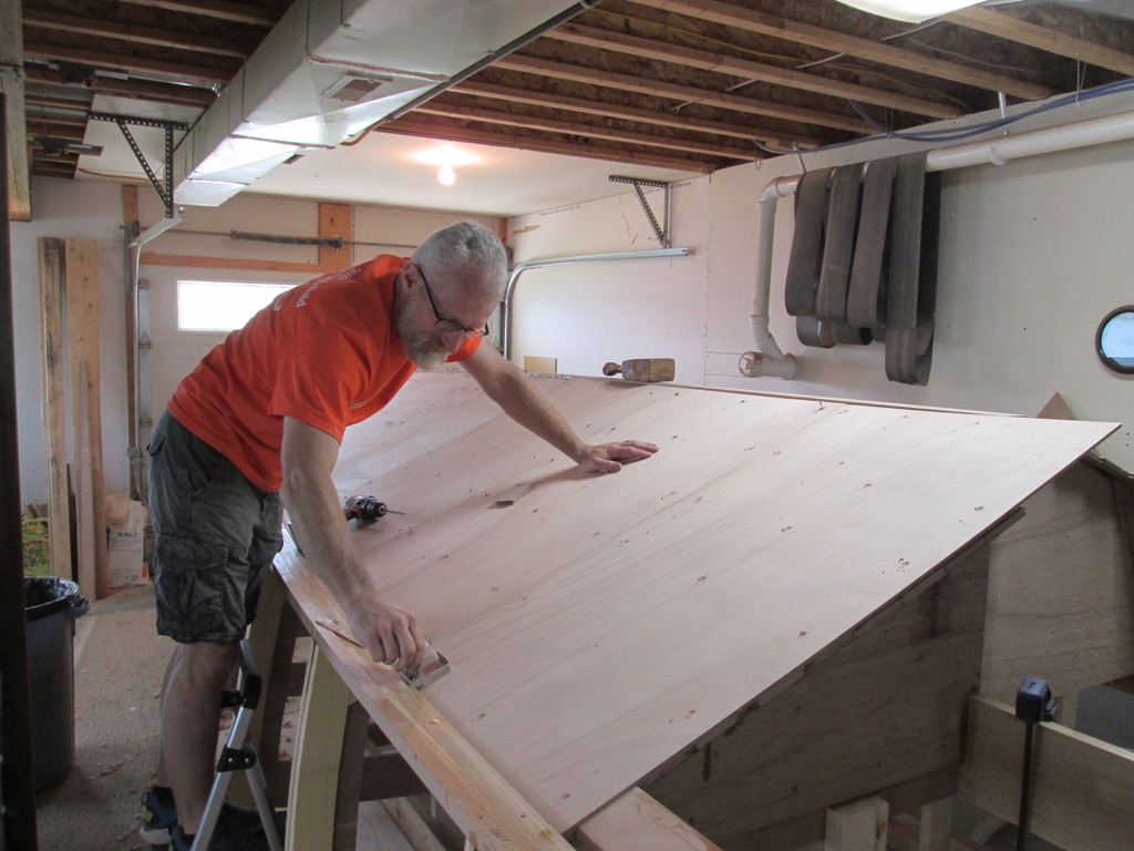
Keel rounded . . . check, chine flat filled with epoxy, front end given overlay bullnose, stern overhangs cut flush, the transom cutout stiffened . . . check, check, check.

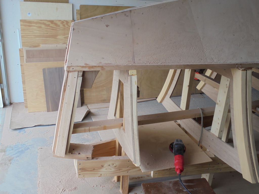
Then the day came to dismantle the strong back. The long screws were taken out to release the 2 x 6’s, and most of the legs of the cross frames removed.

It is now ready get turned over and rest on the cradle, for stage two. . .

Creating the Bow Profile

After the cross frames take shape, the profile of the bow line is the next most important visual. These days a wide variety of design style abounds. The front of Redemption, my first boat, followed the upswept, pointed lines of the long sleek ocean racers.

A more contemporary front design shows a reverse, back-leaning bow line. For a slow moving boat like a cruiser or a sail boat, the result is a longer the water line compared to the width, for better performance. The downside is that especially on faster boats, waves will tend to come up the side easier, making for a wet ride. It is still a visual and functional mystery to me that anyone would use it on a speed boat.

Below is a straight upright bow line, which imitates the tradition of the old runabouts, and looks good sitting still. However, as soon as these boats get moving, they take a plane angle with the bow up, and the front angle tips back awkwardly.

The sketch below by Jeff Margush shows respect for the traditional, neat vertical front angle, but in my opinion will look good sitting or at any position from take off to high speed plane. Of a couple dozen photos and drawings of mine and Jeff’s, this one sits currently at the top of the pile for inspiration. The rake of the windshield may not be imitated . . . this time.

The first experiment extending the front was a cardboard pattern to test the visual sense, which is doubly hard being upside down.

Adding the angled piece below was judged to be too upright.

This is the angle settled upon, and is now rather firmly established, being set in the “concrete” of boat building, epoxy.

Although the side planks will not be permanently fixed until a later stage, I added three on each side just to see if we are headed in the right direction. With some sculptural attention to the chine line, it will eventually “fly.”

7-6. The Fine Art of Fairing

All of the cross frames, and longitudinal moldings and support parts just serve to build support for the shell of the boat, in this case the hull. The intention for the back 6-8 feet is that the surface should be flat for most efficient planing. At first glance the surface below looks flat, and it is pretty close, based on preparation faring work on the frames and stringers.

The tools of the trade for this task are the straight edge, a plane or two, these from Lie-Nielson, and the home made long sanding board.

Pencil marks show where the hull was slightly high, and the block plane or the low angle jack plane start to flatten the area.

Then some sanding with the long board, to only hit the high spots, eventually tames the mildly lumpy surface to a happy, fair curve.

When you are hitting a ball, you have to keep your eye on it, and you might be able to play music by ear. But the if you are testing how well the hills and valleys of a surface are “faired,” the final judge is the hand. You could do it with you eyes closed.